Step 4. FIELD WIRING

Refer to Section A for millivolt appliances and Section B for electronic appliances. The gas valve is set in place and pre-wired at the factory on both models.

A. SIT and Honeywell Millivolt Wiring

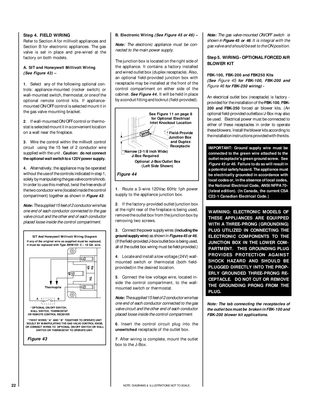
(See Figure 43)

1. Select any of the following optional con- trols: appliance-mounted (rocker switch) or wall-mounted switch, thermostat, or one of the optional remote control kits. If appliance- mounted ON/OFF control is selected mount it in the gas valve mounting bracket.

2. If wall-mounted ON/OFF control or thermo- stat is selected mount it in a convenient location on a wall near the fireplace.

3. Wire the control within the millivolt control circuit using the 15 feet of 2 conductor wire supplied with the unit . Caution: do not connect the optional wall switch to a 120V power supply.

4.Alternatively, the appliance may be operated without the use of the controls indicated in step 1, solely by manipulating the gas valve control knob. In order to use this method, twist the free ends of the two conductor wire (located inside the control compartment) together as shown in Figure 43.

Note: The supplied 15 feet of 2 conductor wire has one end of each conductor connected to the gas valve circuit and the other end of each conductor placed loose inside the control compartment.

SIT And Honeywell Millivolt Wiring Diagram

If any of the original wire as supplied must be replaced, it must be replaced with Type AWM105° C – 18 GA. wire.

B. Electronic Wiring (See Figure 45 or 46)

Note: The electronic appliance must be con- nected to the main power supply.

The junction box is located on the right side of the appliance. It contains a factory installed and wired outlet box (duplex receptacle). Also, an optional field-provided junction box with receptacle may be installed at the front of the control compartment on either side of the cabinet. See Figure 44. It will be held in place by a conduit fitting and locknut (field-provided).

See Figure 11 on page 8

for Optional Electrical

Inlet Knockout Location

*Field-Provide

Junction Box

and Duplex

Receptacle

*Narrow (2-1/8 inch Wide)

J-Box Required

Optional J-Box/Outlet Box

(Left Side Shown)

Figure 44

1. Route a 3-wire 120Vac 60Hz 1ph power supply to the appliance junction box.

2. If the factory-provided outlet/junction box at the right rear of the fireplace is being used, remove the outlet box from the junction box by removing two screws.

3. Connect the power supply wires (including the ground supply wire) as shown in Figures 45 or 46. (If the field-provided J-box/outlet box is being used, all of the outlet box wiring must be field-provided.)

Note: The gas valve-mounted ON/OFF switch is shown in Figure 45 or 46. It is integral with the gas valve and should be set to the ON position.

Step 5. WIRING - OPTIONAL FORCED AIR BLOWER KIT

FBK-100, FBK-200 and FBK250 Kits

(See Figure 45 for FBK-100, FBK-200 and Figure 46 for FBK-250 wiring) -

An electrical outlet box (receptacle) is factory - provided for the installation of the FBK-100, FBK- 200 and FBK-250forced air blower kits. (An optional field-provided outletbox/J-Box may also be used. Electrical power must be connected to either of these receptacles in order to operate these blowers. Install the blower kits according to the installation instructions provided with the kits.

IMPORTANT: Ground supply wire must be connected to the green wire attached to the outlet receptacle's green ground screw. See Figure 45 or 46. Failure to do so will result in a potential safety hazard. The appliance must be electrically grounded in accordance with local codes or, in the absence of local codes, the National Electrical Code, ANSI/NFPA 70- (latest edition). (In Canada, the current CSA C22-1 Canadian Electrical Code.)

WARNING: ELECTRONIC MODELS OF THESE APPLIANCES ARE EQUIPPED WITH A THREE-PRONG (GROUNDING) PLUG UTILIZED IN CONNECTING THE ELECTRONIC COMPONENTS TO THE JUNCTION BOX IN THE LOWER COM- PARTMENT. THIS GROUNDING PLUG PROVIDES PROTECTION AGAINST

TP

Thermopile

A B

*OPTIONAL ON/OFF SWITCH, WALL SWITCH, THERMOSTAT OR REMOTE CONTROL RECEIVER

TH TH TP

4. Locate and install a low voltage (24V) wall- mounted switch or thermostat (both field- provided)in the desired location.

5. Connect the low voltage wire, located in- side the control compartment, to the wall- mounted switch or thermostat.

Note: The supplied 15 feet of 2 conductor wire has one end of each conductor connected to the gas valve circuit and the other end of each conductor placed loose inside the control compartment.

SHOCK HAZARD AND SHOULD BE PLUGGED DIRECTLY INTO THE PROP- ERLY GROUNDED THREE-PRONG RE- CEPTACLE. DO NOT CUT OR REMOVE THE GROUNDING PRONG FROM THE PLUG.

Note: The tab connecting the receptacles of the outlet box must be broken in FBK-100 and FBK-200 blower kit applications.

22

*TWIST WIRES “A” AND “B” TOGETHER TO OPERATE UNIT SOLELY BY MANIPULATING THE GAS VALVE CONTROL KNOB; OR CONNECT WIRES TO OPTIONAL ON/OFF SWITCH OR WALL SWITCH OR THERMOSTAT TO OPERATE UNIT.

Figure 43

6. Insert the control circuit plug into the unswitched receptacle of the outlet box.

7. After wiring is complete, mount the outlet box to the J-Box.

NOTE: DIAGRAMS & ILLUSTRATIONS NOT TO SCALE.

Page 22
Image 22
Lennox Hearth MPD-35 Series Field Wiring, Wiring Optional Forced AIR Blower KIT, SIT and Honeywell Millivolt Wiring

MPD-35 Series, MPD-45 Series, MPD-33 Series, MPD-40 Series specifications

The Lennox Hearth MPD-33, MPD-40, MPD-45, and MPD-35 Series are sophisticated and innovative products designed for both aesthetic appeal and functional heating efficiency. These multi-sided gas fireplaces are engineered to bring warmth and style to any space, making them a popular choice for homeowners looking to enhance their living environment.

One of the standout features of the MPD Series is their versatile design. Each model is available in different sizes with stylish options, catering to various room dimensions and decor styles. The MPD-33, MPD-40, and MPD-45 models provide flexibility in installation, while the MPD-35 offers extra depth for a more pronounced fire presence, making them suitable for both contemporary and traditional interiors.

A key characteristic of the Lennox Hearth MPD Series is its high-efficiency operation. These fireplaces are designed to maximize heat output while minimizing fuel consumption, resulting in lower energy bills. The innovative burner system produces a realistic flame effect that can be adjusted to create the perfect ambiance for any occasion. The use of advanced technology ensures that the heat generated is evenly distributed, enhancing overall comfort.

Safety is paramount in the design of the MPD Series. Each model is equipped with a state-of-the-art safety shut-off system that activates if the flame goes out, ensuring peace of mind for users. Additionally, the glass front not only provides a clear view of the flames but is designed to stay cool to the touch, making it safe for families with children and pets.

The efficiency of these models is further complemented by an optional remote control feature, allowing users to adjust the flame height and thermostat settings with ease. The MPD Series is also compatible with smart home systems, providing users with added convenience.

Overall, the Lennox Hearth MPD-33, MPD-40, MPD-45, and MPD-35 Series exemplify the perfect combination of efficiency, safety, and design. Their ability to blend function with visual appeal makes them an ideal choice for creating a cozy atmosphere in any room, from living areas to bedrooms. These fireplaces stand as a testament to Lennox's commitment to quality and innovation in home heating solutions. With advanced technologies and a focus on user comfort, the MPD Series is designed to meet the needs of modern homeowners seeking reliable and stylish heating options.