VENT

REARVENT

APPLICATION


REAR

TOP


VENT


APPLICATION

APPLICATION


APPLICATION


APPLICATION

APPLICATION


TOP VENT

TOP VENT

TOP VENT


APPLICATION


RECESSED


TOP VENT


INSTALLATION


TOP VENT


APPLICATION


Figure 2


HORIZONTAL VENT

HORIZONTAL VENT


HORIZONTAL VENT

VERTICAL VENT


VERTICAL VENT


(Rear Vent Application

(Rear Vent Application

(Top Vent

(Top Vent


(Rear Vent


without a chase)

With a chase)

Application)

Application)


Application)


Typical Locations

LOCATION

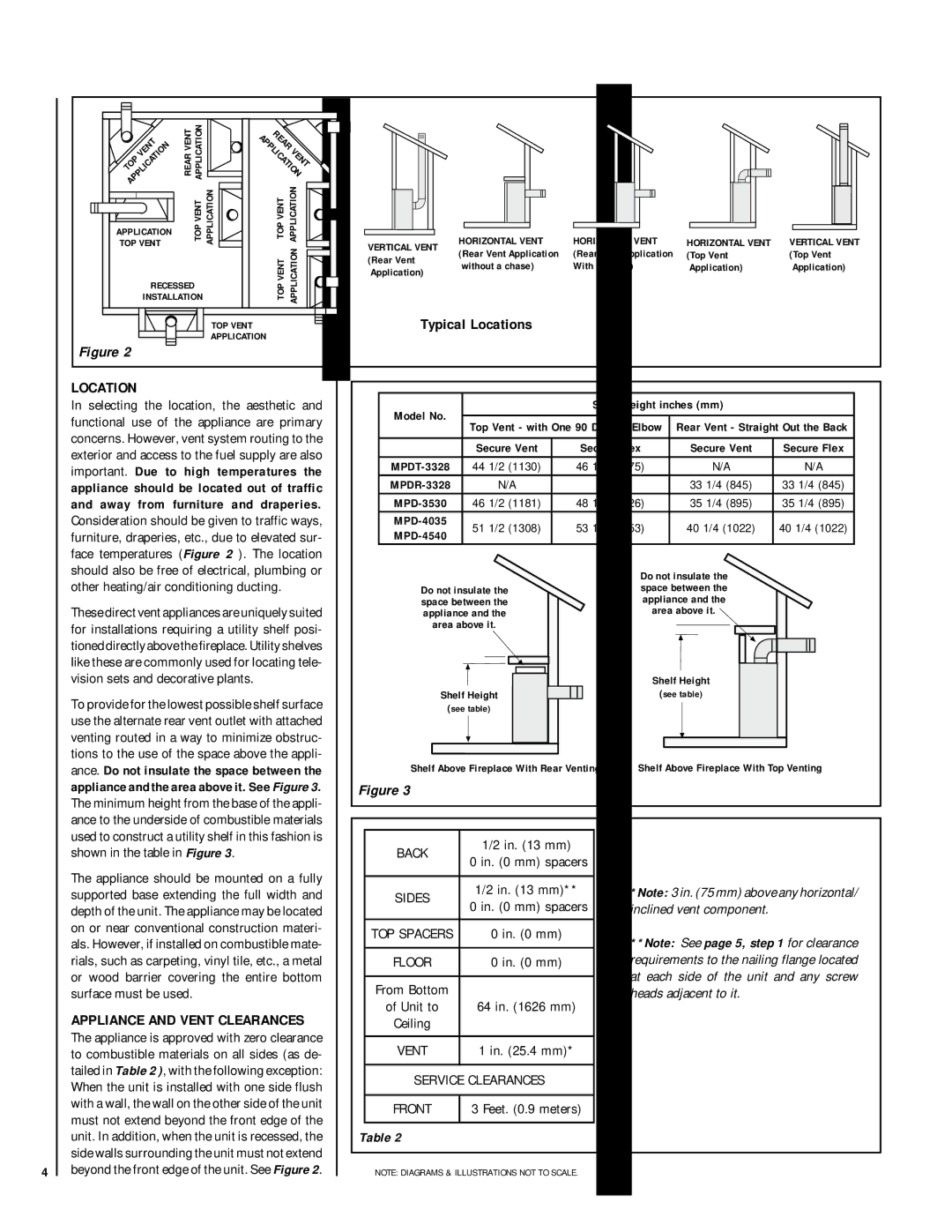
In selecting the location, the aesthetic and functional use of the appliance are primary concerns. However, vent system routing to the exterior and access to the fuel supply are also important. Due to high temperatures the appliance should be located out of traffic and away from furniture and draperies. Consideration should be given to traffic ways, furniture, draperies, etc., due to elevated sur- face temperatures (Figure 2 ). The location should also be free of electrical, plumbing or

Model No.


Shelf Height inches (mm)


Top Vent - with One 90 Degree Elbow

Rear Vent - Straight Out the Back


Secure Vent

Secure Flex

Secure Vent

Secure Flex

MPDT-3328

44 1/2 (1130)

46 1/4 (1175)

N/A

N/A

MPDR-3328

N/A

N/A

33 1/4 (845)

33 1/4 (845)

MPD-3530

46 1/2 (1181)

48 1/4 (1226)

35 1/4 (895)

35 1/4 (895)

MPD-4035

51 1/2 (1308)

53 1/4 (1353)

40 1/4 (1022)

40 1/4 (1022)

MPD-4540


other heating/air conditioning ducting.

These direct vent appliances are uniquely suited for installations requiring a utility shelf posi- tioned directly above the fireplace. Utility shelves like these are commonly used for locating tele- vision sets and decorative plants.

To provide for the lowest possible shelf surface use the alternate rear vent outlet with attached venting routed in a way to minimize obstruc- tions to the use of the space above the appli-

Do not insulate the space between the appliance and the area above it.

Shelf Height

(see table)

Do not insulate the space between the appliance and the area above it.

Shelf Height

(see table)

ance. Do not insulate the space between the appliance and the area above it. See Figure 3.

Shelf Above Fireplace With Rear Venting

Shelf Above Fireplace With Top Venting

Figure 3

The minimum height from the base of the appli- ance to the underside of combustible materials used to construct a utility shelf in this fashion is shown in the table in Figure 3.

The appliance should be mounted on a fully supported base extending the full width and depth of the unit. The appliance may be located on or near conventional construction materi- als. However, if installed on combustible mate- rials, such as carpeting, vinyl tile, etc., a metal or wood barrier covering the entire bottom surface must be used.

APPLIANCE AND VENT CLEARANCES

The appliance is approved with zero clearance to combustible materials on all sides (as de- tailed in Table 2 ), with the following exception: When the unit is installed with one side flush with a wall, the wall on the other side of the unit must not extend beyond the front edge of the unit. In addition, when the unit is recessed, the side walls surrounding the unit must not extend beyond the front edge of the unit. See Figure 2.

BACK

1/2 in. (13 mm)

0 in. (0 mm) spacers


SIDES

1/2 in. (13 mm)**

0 in. (0 mm) spacers


TOP SPACERS

0 in. (0 mm)


FLOOR

0 in. (0 mm)


From Bottom


of Unit to

64 in. (1626 mm)

Ceiling


VENT

1 in. (25.4 mm)*


SERVICE CLEARANCES


FRONT

3 Feet. (0.9 meters)


Table 2

*Note: 3 in. (75 mm) above any horizontal/ inclined vent component.

**Note: See page 5, step 1 for clearance requirements to the nailing flange located at each side of the unit and any screw heads adjacent to it.

4

NOTE: DIAGRAMS & ILLUSTRATIONS NOT TO SCALE.

Page 4
Image 4
Lennox Hearth MPD-45 Series Typical Locations, Appliance and Vent Clearances, Other heating/air conditioning ducting

MPD-35 Series, MPD-45 Series, MPD-33 Series, MPD-40 Series specifications

The Lennox Hearth MPD-33, MPD-40, MPD-45, and MPD-35 Series are sophisticated and innovative products designed for both aesthetic appeal and functional heating efficiency. These multi-sided gas fireplaces are engineered to bring warmth and style to any space, making them a popular choice for homeowners looking to enhance their living environment.

One of the standout features of the MPD Series is their versatile design. Each model is available in different sizes with stylish options, catering to various room dimensions and decor styles. The MPD-33, MPD-40, and MPD-45 models provide flexibility in installation, while the MPD-35 offers extra depth for a more pronounced fire presence, making them suitable for both contemporary and traditional interiors.

A key characteristic of the Lennox Hearth MPD Series is its high-efficiency operation. These fireplaces are designed to maximize heat output while minimizing fuel consumption, resulting in lower energy bills. The innovative burner system produces a realistic flame effect that can be adjusted to create the perfect ambiance for any occasion. The use of advanced technology ensures that the heat generated is evenly distributed, enhancing overall comfort.

Safety is paramount in the design of the MPD Series. Each model is equipped with a state-of-the-art safety shut-off system that activates if the flame goes out, ensuring peace of mind for users. Additionally, the glass front not only provides a clear view of the flames but is designed to stay cool to the touch, making it safe for families with children and pets.

The efficiency of these models is further complemented by an optional remote control feature, allowing users to adjust the flame height and thermostat settings with ease. The MPD Series is also compatible with smart home systems, providing users with added convenience.

Overall, the Lennox Hearth MPD-33, MPD-40, MPD-45, and MPD-35 Series exemplify the perfect combination of efficiency, safety, and design. Their ability to blend function with visual appeal makes them an ideal choice for creating a cozy atmosphere in any room, from living areas to bedrooms. These fireplaces stand as a testament to Lennox's commitment to quality and innovation in home heating solutions. With advanced technologies and a focus on user comfort, the MPD Series is designed to meet the needs of modern homeowners seeking reliable and stylish heating options.