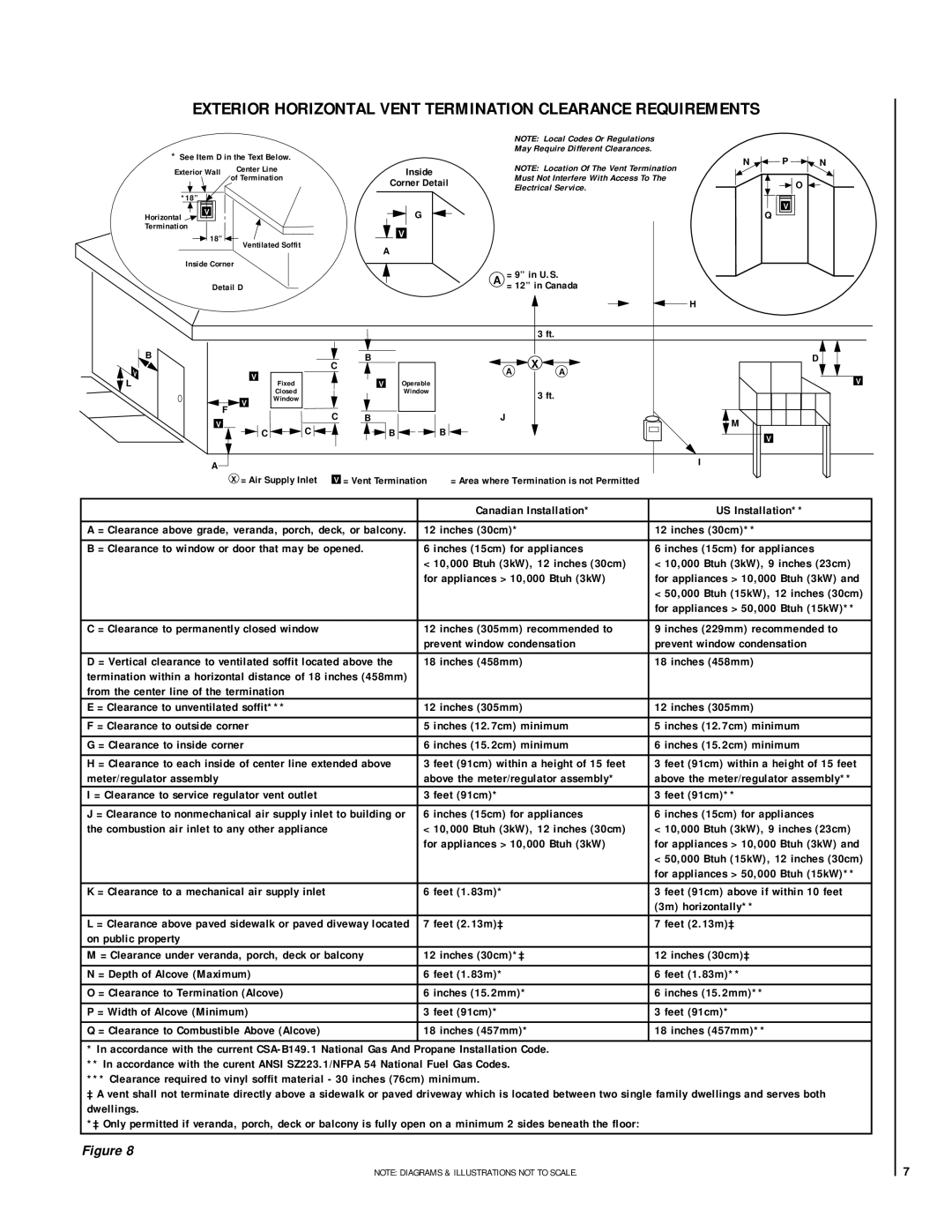
EXTERIOR HORIZONTAL VENT TERMINATION CLEARANCE REQUIREMENTS

*See Item D in the Text Below.


Exterior Wall

Center Line


of Termination


*18”


Horizontal

V


Termination


18”

Ventilated Soffit


Inside Corner


Detail D


B


C


V


L


Fixed


Closed


F

V

Window


C


V


C

C


A


X = Air Supply Inlet

V


NOTE: Local Codes Or Regulations


May Require Different Clearances.


Inside


NOTE: Location Of The Vent Termination

Corner Detail


Must Not Interfere With Access To The


Electrical Service.


G


V


A


A

= 9” in U.S.


= 12” in Canada


H


3 ft.

B


X


A


A

V

Operable


Window


3 ft.


B


J


B

B


I

= Vent Termination = Area where Termination is not Permitted

N P N

O

V

Q

D

V

M

V


Canadian Installation*

US Installation**


A = Clearance above grade, veranda, porch, deck, or balcony.

12 inches (30cm)*

12 inches (30cm)**

B = Clearance to window or door that may be opened.

6 inches (15cm) for appliances

6 inches (15cm) for appliances


< 10,000 Btuh (3kW), 12 inches (30cm)

< 10,000 Btuh (3kW), 9 inches (23cm)


for appliances > 10,000 Btuh (3kW)

for appliances > 10,000 Btuh (3kW) and


< 50,000 Btuh (15kW), 12 inches (30cm)


for appliances > 50,000 Btuh (15kW)**


C = Clearance to permanently closed window

12 inches (305mm) recommended to

9 inches (229mm) recommended to


prevent window condensation

prevent window condensation


D = Vertical clearance to ventilated soffit located above the

18 inches (458mm)

18 inches (458mm)

termination within a horizontal distance of 18 inches (458mm)


from the center line of the termination


E = Clearance to unventilated soffit***

12 inches (305mm)

12 inches (305mm)

F = Clearance to outside corner

5 inches (12.7cm) minimum

5 inches (12.7cm) minimum


G = Clearance to inside corner

6 inches (15.2cm) minimum

6 inches (15.2cm) minimum


H = Clearance to each inside of center line extended above

3 feet (91cm) within a height of 15 feet

3 feet (91cm) within a height of 15 feet

meter/regulator assembly

above the meter/regulator assembly*

above the meter/regulator assembly**

I = Clearance to service regulator vent outlet

3 feet (91cm)*

3 feet (91cm)**


J = Clearance to nonmechanical air supply inlet to building or

6 inches (15cm) for appliances

6 inches (15cm) for appliances

the combustion air inlet to any other appliance

< 10,000 Btuh (3kW), 12 inches (30cm)

< 10,000 Btuh (3kW), 9 inches (23cm)


for appliances > 10,000 Btuh (3kW)

for appliances > 10,000 Btuh (3kW) and


< 50,000 Btuh (15kW), 12 inches (30cm)


for appliances > 50,000 Btuh (15kW)**

K = Clearance to a mechanical air supply inlet

6 feet (1.83m)*

3 feet (91cm) above if within 10 feet


(3m) horizontally**

L = Clearance above paved sidewalk or paved diveway located

7 feet (2.13m)‡

7 feet (2.13m)‡

on public property


M = Clearance under veranda, porch, deck or balcony

12 inches (30cm)*‡

12 inches (30cm)‡


N = Depth of Alcove (Maximum)

6 feet (1.83m)*

6 feet (1.83m)**


O = Clearance to Termination (Alcove)

6 inches (15.2mm)*

6 inches (15.2mm)**

P = Width of Alcove (Minimum)

3 feet (91cm)*

3 feet (91cm)*

Q = Clearance to Combustible Above (Alcove)

18 inches (457mm)*

18 inches (457mm)**


* In accordance with the current CSA-B149.1 National Gas And Propane Installation Code.


** In accordance with the curent ANSI SZ223.1/NFPA 54 National Fuel Gas Codes.


*** Clearance required to vinyl soffit material - 30 inches (76cm) minimum.


‡ A vent shall not terminate directly above a sidewalk or paved driveway which is located between two single family dwellings and serves both

dwellings.


*‡ Only permitted if veranda, porch, deck or balcony is fully open on a minimum 2 sides beneath the floor:


Figure 8


NOTE: DIAGRAMS & ILLUSTRATIONS NOT TO SCALE.

7

Page 7
Image 7
Lennox Hearth MPD-33 Series Canadian Installation US Installation, Inches 30cm, Inches 15cm for appliances, Inches 458mm

MPD-35 Series, MPD-45 Series, MPD-33 Series, MPD-40 Series specifications

The Lennox Hearth MPD-33, MPD-40, MPD-45, and MPD-35 Series are sophisticated and innovative products designed for both aesthetic appeal and functional heating efficiency. These multi-sided gas fireplaces are engineered to bring warmth and style to any space, making them a popular choice for homeowners looking to enhance their living environment.

One of the standout features of the MPD Series is their versatile design. Each model is available in different sizes with stylish options, catering to various room dimensions and decor styles. The MPD-33, MPD-40, and MPD-45 models provide flexibility in installation, while the MPD-35 offers extra depth for a more pronounced fire presence, making them suitable for both contemporary and traditional interiors.

A key characteristic of the Lennox Hearth MPD Series is its high-efficiency operation. These fireplaces are designed to maximize heat output while minimizing fuel consumption, resulting in lower energy bills. The innovative burner system produces a realistic flame effect that can be adjusted to create the perfect ambiance for any occasion. The use of advanced technology ensures that the heat generated is evenly distributed, enhancing overall comfort.

Safety is paramount in the design of the MPD Series. Each model is equipped with a state-of-the-art safety shut-off system that activates if the flame goes out, ensuring peace of mind for users. Additionally, the glass front not only provides a clear view of the flames but is designed to stay cool to the touch, making it safe for families with children and pets.

The efficiency of these models is further complemented by an optional remote control feature, allowing users to adjust the flame height and thermostat settings with ease. The MPD Series is also compatible with smart home systems, providing users with added convenience.

Overall, the Lennox Hearth MPD-33, MPD-40, MPD-45, and MPD-35 Series exemplify the perfect combination of efficiency, safety, and design. Their ability to blend function with visual appeal makes them an ideal choice for creating a cozy atmosphere in any room, from living areas to bedrooms. These fireplaces stand as a testament to Lennox's commitment to quality and innovation in home heating solutions. With advanced technologies and a focus on user comfort, the MPD Series is designed to meet the needs of modern homeowners seeking reliable and stylish heating options.