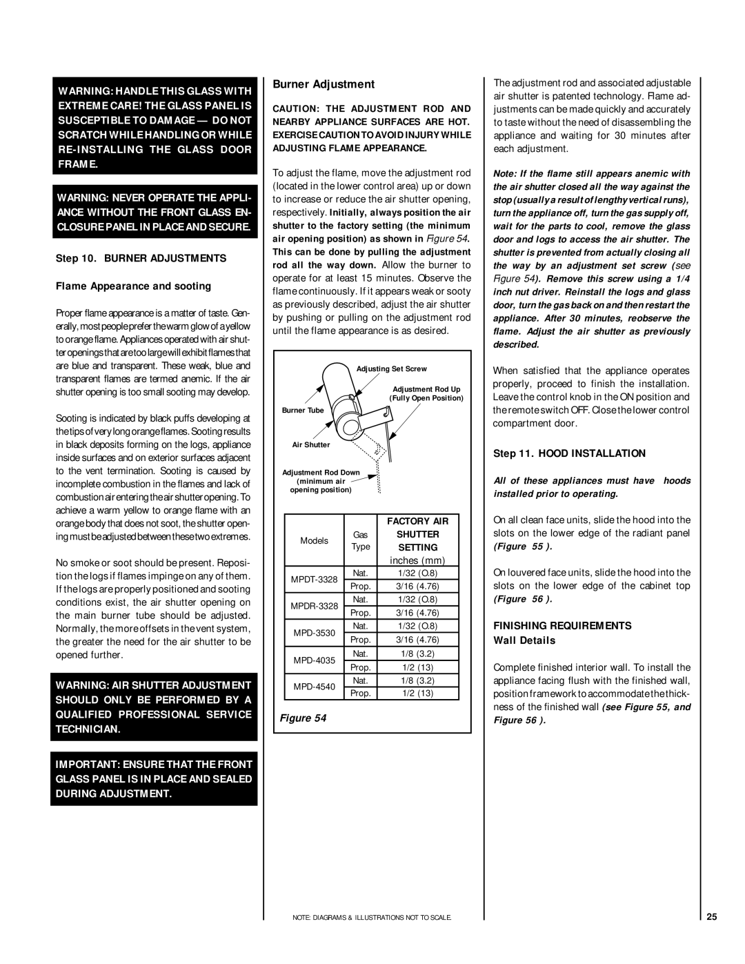
MPD-35 Series, MPD-45 Series, MPD-33 Series, MPD-40 Series specifications
The Lennox Hearth MPD-33, MPD-40, MPD-45, and MPD-35 Series are sophisticated and innovative products designed for both aesthetic appeal and functional heating efficiency. These multi-sided gas fireplaces are engineered to bring warmth and style to any space, making them a popular choice for homeowners looking to enhance their living environment.One of the standout features of the MPD Series is their versatile design. Each model is available in different sizes with stylish options, catering to various room dimensions and decor styles. The MPD-33, MPD-40, and MPD-45 models provide flexibility in installation, while the MPD-35 offers extra depth for a more pronounced fire presence, making them suitable for both contemporary and traditional interiors.
A key characteristic of the Lennox Hearth MPD Series is its high-efficiency operation. These fireplaces are designed to maximize heat output while minimizing fuel consumption, resulting in lower energy bills. The innovative burner system produces a realistic flame effect that can be adjusted to create the perfect ambiance for any occasion. The use of advanced technology ensures that the heat generated is evenly distributed, enhancing overall comfort.
Safety is paramount in the design of the MPD Series. Each model is equipped with a state-of-the-art safety shut-off system that activates if the flame goes out, ensuring peace of mind for users. Additionally, the glass front not only provides a clear view of the flames but is designed to stay cool to the touch, making it safe for families with children and pets.
The efficiency of these models is further complemented by an optional remote control feature, allowing users to adjust the flame height and thermostat settings with ease. The MPD Series is also compatible with smart home systems, providing users with added convenience.
Overall, the Lennox Hearth MPD-33, MPD-40, MPD-45, and MPD-35 Series exemplify the perfect combination of efficiency, safety, and design. Their ability to blend function with visual appeal makes them an ideal choice for creating a cozy atmosphere in any room, from living areas to bedrooms. These fireplaces stand as a testament to Lennox's commitment to quality and innovation in home heating solutions. With advanced technologies and a focus on user comfort, the MPD Series is designed to meet the needs of modern homeowners seeking reliable and stylish heating options.

