Gas Piping

Gas supply piping should not allow more than 0.5”W.C. drop in pressure between gas meter and unit. Supply gas pipe must not be smaller than unit gas connection.

CAUTION

If a flexible gas connector is required or allowed by the authority that has jurisdiction, black iron pipe shall be installed at the gas valve and extend outside the furnace cabinet. The flexible connector can then be added between the black iron pipe and the gas supply line.

WARNING

Do not exceed 600 in-lbs (50 ft-lbs) torque when at­ taching the gas piping to the gas valve.

1 - Gas piping may be routed into the unit through either the left‐ or right‐hand side. Supply piping enters into the gas valve from the side of the valve as shown in figure 61.

2 - When connecting gas supply, factors such as length of run, number of fittings and furnace rating must be con­ sidered to avoid excessive pressure drop. Table 10 lists recommended pipe sizes for typical applications.

NOTE - Use two wrenches when connecting gas pip­ ing to avoid transferring torque to the manifold.

3 - Gas piping must not run in or through air ducts, clothes chutes, chimneys or gas vents, dumb waiters or eleva­ tor shafts. Center gas line through piping hole. Gas line should not touch side of unit. See figures 61 and 62.

4 - Piping should be sloped 1/4 inch per 15 feet (6mm per 5.6m) upward toward the gas meter from the furnace. The piping must be supported at proper intervals, ev­ ery 8 to 10 feet (2.44 to 3.05m), using suitable hangers or straps. Install a drip leg in vertical pipe runs to serve as a trap for sediment or condensate.

5 - A 1/8” N.P.T. plugged tap or pressure post is located on the gas valve to facilitate test gauge connection. See figure 66.

6 - In some localities, codes may require installation of a manual main shut‐off valve and union (furnished by in­ staller) external to the unit. Union must be of the ground joint type.

IMPORTANT

Compounds used on threaded joints of gas piping must be resistant to the actions of liquified petro­ leum gases.

Leak Check

After gas piping is completed, carefully check all piping connections (factory- and field-installed) for gas leaks. Use a leak detecting solution or other preferred means.

Never use an open flame to test for gas leaks. Check all connections using a commercially available soap solution made specifically for leak detection.

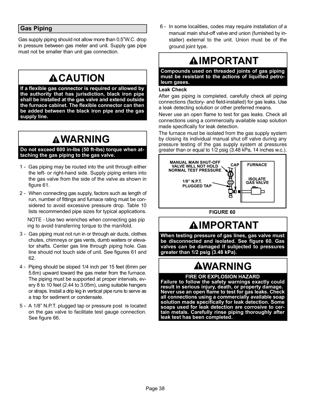
The furnace must be isolated from the gas supply system by closing its individual manual shut‐off valve during any pressure testing of the gas supply system at pressures greater than or equal to 1/2 psig (3.48 kPa, 14 inches w.c.).

MANUAL MAIN SHUT-OFF

VALVE WILL NOT HOLD CAP FURNACE NORMAL TEST PRESSURE

1/8” N.P.T.

ISOLATE

GAS VALVE

PLUGGED TAP


FIGURE 60

IMPORTANT

When testing pressure of gas lines, gas valve must be disconnected and isolated. See figure 60. Gas

valves can be damaged if subjected to pressures

greater than 1/2 psig (3.48 kPa).

WARNING

FIRE OR EXPLOSION HAZARD

Failure to follow the safety warnings exactly could result in serious injury, death, or property damage. Never use an open flame to test for gas leaks. Check all connections using a commercially available soap solution made specifically for leak detection. Some soaps used for leak detection are corrosive to cer­ tain metals. Carefully rinse piping thoroughly after leak test has been completed.

Page 38

Page 38
Image 38
Lennox International Inc EL296UHE, Elite Series Gas Furnace installation instructions Gas Piping, Leak Check, Plugged TAP

EL296UHE, Elite Series Gas Furnace specifications

Lennox International Inc. has long been a trusted name in the heating, ventilation, and air conditioning (HVAC) industry, and their Elite Series Gas Furnace, the EL296UHE, stands out as a remarkable choice for homeowners seeking efficiency and reliability. This gas furnace is designed to deliver exceptional performance while ensuring the comfort of your living space.

One of the most significant features of the EL296UHE is its impressive Annual Fuel Utilization Efficiency (AFUE) rating of up to 96%. This means that a substantial portion of the energy consumed is converted into heat, translating to lower energy bills and a reduced environmental footprint. By minimizing energy waste, homeowners can enjoy both cost savings and greater environmental responsibility.

The EL296UHE is equipped with a two-stage heating process that allows it to operate at different speeds. This dual-stage functionality offers a more consistent temperature throughout the home, minimizing cold spots and enhancing overall comfort. Additionally, this furnace features a variable-speed blower motor, which not only improves the distribution of heated air but also quietly adjusts the airflow to match the heating requirements of your space.

In terms of technology, the EL296UHE incorporates advanced design elements such as a patented ZenBalanceā„¢ technology. This innovation further increases efficiency by adjusting the heating output based on real-time demands, ensuring optimal comfort without excessive energy consumption.

Durability is another hallmark of the EL296UHE. Constructed with high-quality materials, this furnace is built to withstand the rigors of daily use. Its stainless-steel heat exchanger is particularly noteworthy, as it enhances the furnace's ability to operate efficiently while maximizing longevity.

Homeowners are also reassured by the EL296UHE's quiet operation. The design minimizes operational noise, making it an ideal choice for those who prefer a peaceful home environment. Furthermore, the furnace is equipped with an ENERGY STARĀ® certification, a testament to its energy-efficient performance.

Lastly, Lennox offers comprehensive warranties for the EL296UHE, ensuring peace of mind for consumers. The combination of high efficiency, advanced technology, and durability makes the Lennox Elite Series Gas Furnace, EL296UHE, an excellent investment for homeowners looking to enhance their heating systems for optimal comfort and efficiency.