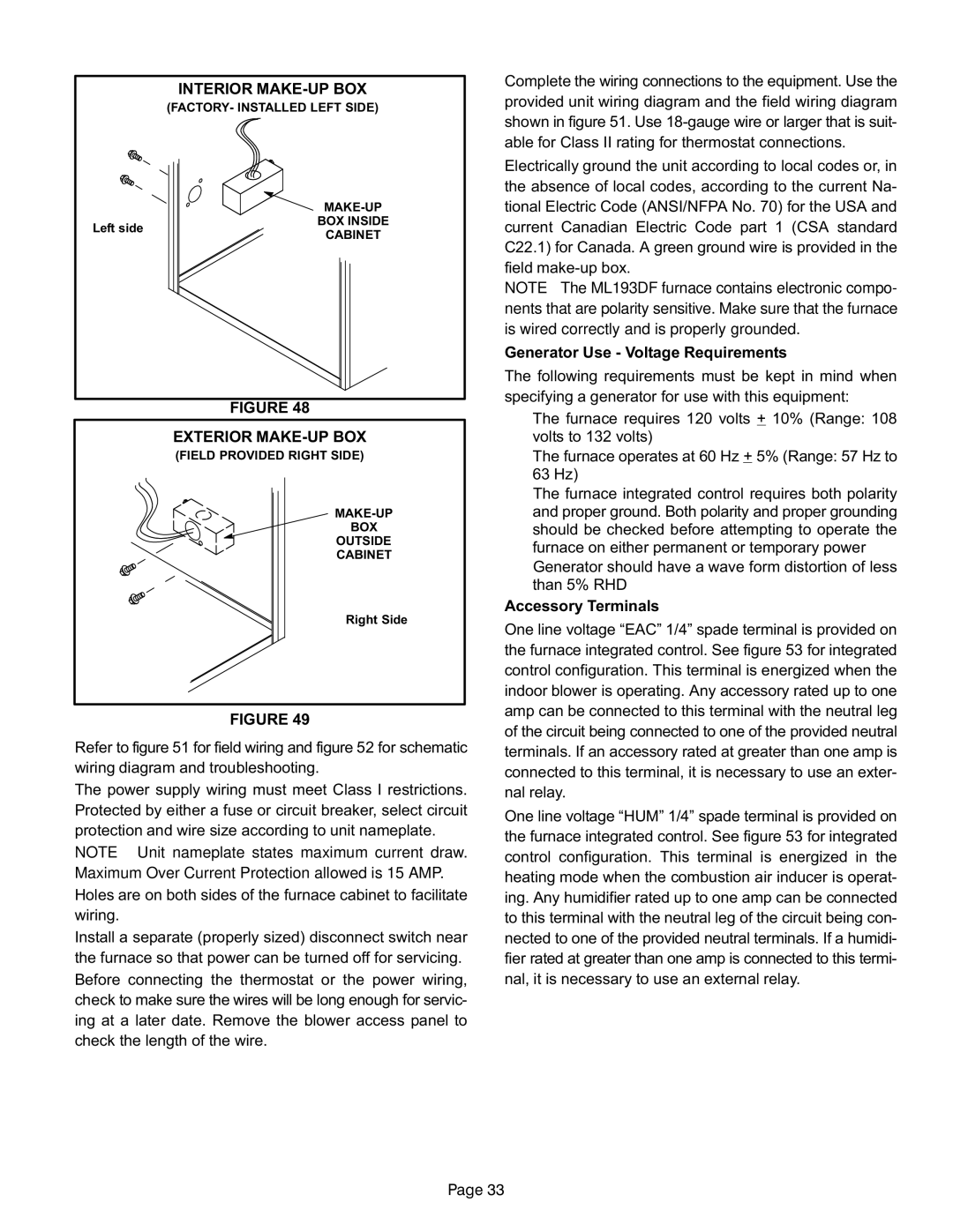
INTERIOR MAKE−UP BOX
(FACTORY− INSTALLED LEFT SIDE)
| MAKE−UP | |
Left side | BOX INSIDE | |
CABINET | ||
|
FIGURE 48
EXTERIOR MAKE−UP BOX
(FIELD PROVIDED RIGHT SIDE)
MAKE−UP
BOX
OUTSIDE
CABINET
Right Side
FIGURE 49
Refer to figure 51 for field wiring and figure 52 for schematic wiring diagram and troubleshooting.
The power supply wiring must meet Class I restrictions. Protected by either a fuse or circuit breaker, select circuit protection and wire size according to unit nameplate.
NOTE − Unit nameplate states maximum current draw. Maximum Over−Current Protection allowed is 15 AMP. Holes are on both sides of the furnace cabinet to facilitate wiring.
Install a separate (properly sized) disconnect switch near the furnace so that power can be turned off for servicing. Before connecting the thermostat or the power wiring, check to make sure the wires will be long enough for servic- ing at a later date. Remove the blower access panel to check the length of the wire.
Complete the wiring connections to the equipment. Use the provided unit wiring diagram and the field wiring diagram shown in figure 51. Use 18−gauge wire or larger that is suit- able for Class II rating for thermostat connections.
Electrically ground the unit according to local codes or, in the absence of local codes, according to the current Na- tional Electric Code (ANSI/NFPA No. 70) for the USA and current Canadian Electric Code part 1 (CSA standard C22.1) for Canada. A green ground wire is provided in the field make−up box.
NOTE − The ML193DF furnace contains electronic compo- nents that are polarity sensitive. Make sure that the furnace is wired correctly and is properly grounded.
Generator Use − Voltage Requirements
The following requirements must be kept in mind when specifying a generator for use with this equipment:
D The furnace requires 120 volts + 10% (Range: 108 volts to 132 volts)
DThe furnace operates at 60 Hz + 5% (Range: 57 Hz to 63 Hz)
DThe furnace integrated control requires both polarity and proper ground. Both polarity and proper grounding should be checked before attempting to operate the furnace on either permanent or temporary power
DGenerator should have a wave form distortion of less than 5% RHD
Accessory Terminals
One line voltage ade terminal is provided on
the furnace integrated control. See figure 53 for integrated control configuration. This terminal is energized when the indoor blower is operating. Any accessory rated up to one amp can be connected to this terminal with the neutral leg of the circuit being connected to one of the provided neutral terminals. If an accessory rated at greater than one amp is connected to this terminal, it is necessary to use an exter- nal relay.
One line voltage ade terminal is provided on
the furnace integrated control. See figure 53 for integrated control configuration. This terminal is energized in the heating mode when the combustion air inducer is operat- ing. Any humidifier rated up to one amp can be connected to this terminal with the neutral leg of the circuit being con- nected to one of the provided neutral terminals. If a humidi- fier rated at greater than one amp is connected to this termi- nal, it is necessary to use an external relay.
Page 33