4.Remove all memory modules and PCI cards that are currently installed. See “Installing or replacing a memory module” on page 36 and “Installing or replacing a PCI card” on page 32.
5.Remove the secondary hard disk drive. See “Replacing the secondary hard disk drive” on page 40.
6.Remove the heat sink and fan assembly from the failing system board. See “Replacing the heat sink and fan assembly” on page 44.
7.Remove the microprocessor from the failing system board. See “Replacing the microprocessor” on page 45.
8.Remove the battery from the failing system board. See “Replacing the battery” on page 35.
9.Note the location of all cable connections on the system board and disconnect all cables. See
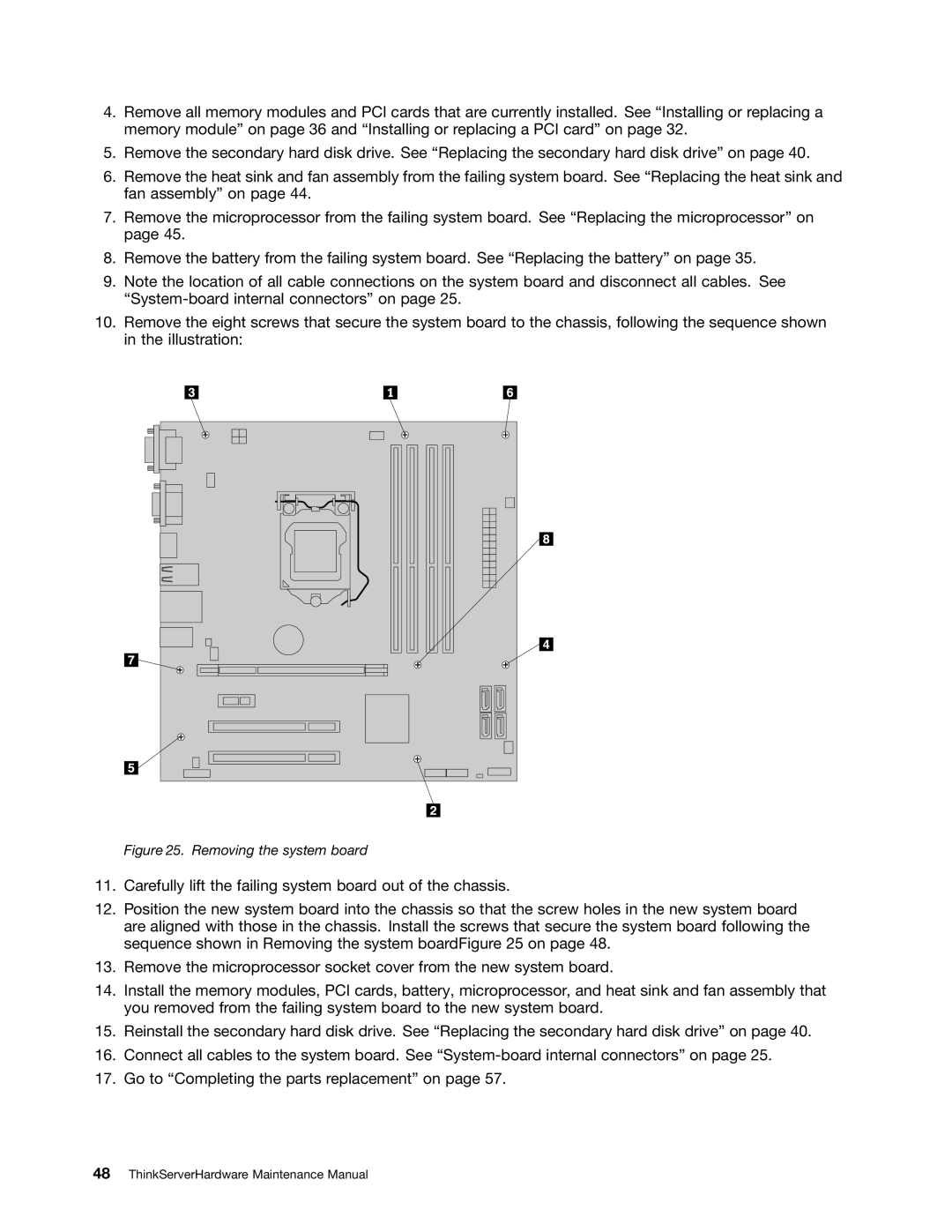
10.Remove the eight screws that secure the system board to the chassis, following the sequence shown in the illustration:
Figure 25. Removing the system board
11.Carefully lift the failing system board out of the chassis.
12.Position the new system board into the chassis so that the screw holes in the new system board are aligned with those in the chassis. Install the screws that secure the system board following the sequence shown in Removing the system boardFigure 25 on page 48.
13.Remove the microprocessor socket cover from the new system board.
14.Install the memory modules, PCI cards, battery, microprocessor, and heat sink and fan assembly that you removed from the failing system board to the new system board.
15.Reinstall the secondary hard disk drive. See “Replacing the secondary hard disk drive” on page 40.
16.Connect all cables to the system board. See
17.Go to “Completing the parts replacement” on page 57.
