When the power is turned on, the computer returns from hibernation mode and resumes operation. The hibernation file in the boot record on the hard disk drive is read, and system status is restored from the hard disk drive.
Wireless off mode
In wireless off mode, the wireless features are turned off to conserve power. To turn off or turn on the wireless features, press F8.
Symptom-to-FRU index
This section contains following information:
•“Numeric error codes” on page 36
•“Error messages” on page 38
•
•
•“Intermittent problems” on page 39
•“Undetermined problems” on page 39
The
Note: Do the FRU replacement or other actions in the sequence shown in the column headed “FRU or action, in sequence.” If replacing a FRU does not solve the problem, put the original part back in the computer. Do not replace a nondefective FRU.
This index can also help you determine, during regular servicing, what FRUs are likely to need to be replaced next.
A numeric error is displayed for each error detected in POST or system operation. In the displays, n can be any number.
If no numeric code is displayed, check the narrative descriptions of symptoms. If the symptom is not described there, go to “Intermittent problems” on page 39.
Note: For a device not supported by diagnostic codes in the ThinkPad notebook computers, see the manual for that device.
Numeric error codes
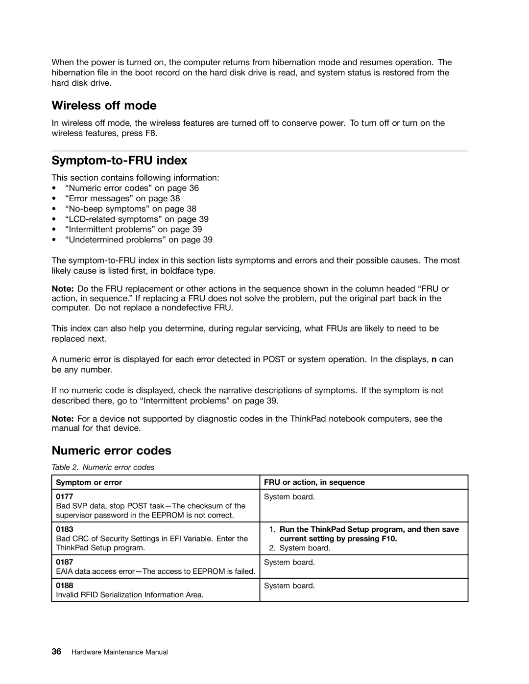
Table 2. Numeric error codes
Symptom or error | FRU or action, in sequence |
|
|
0177 | System board. |
Bad SVP data, stop POST |
|
supervisor password in the EEPROM is not correct. |
|
|
|
0183 | 1. Run the ThinkPad Setup program, and then save |
Bad CRC of Security Settings in EFI Variable. Enter the | current setting by pressing F10. |
ThinkPad Setup program. | 2. System board. |
|
|
0187 | System board. |
EAIA data access |
|
|
|
0188 | System board. |
Invalid RFID Serialization Information Area. |
|
|
|