ThinkPad S230u
Hardware Maintenance Manual
First Edition September Copyright Lenovo
Contents
Appendix A. Notices
Iii
About this manual
Iv Hardware Maintenance Manual
General safety
Safety information
Electrical safety
Safety inspection guide
Grounding requirements
Safety notices multilingual translations
Safety information
Hardware Maintenance Manual
Safety information
Perigo
Perigo
Vorsicht
Vorsicht
Vorsicht
Safety information
Hardware Maintenance Manual
Safety information
Hardware Maintenance Manual
Safety information
Hardware Maintenance Manual
Safety information
Hardware Maintenance Manual
Before replacing parts
Important service information
Strategy for replacing FRUs
Select Drivers & Software
How to use error message
Dynamic Configure To Order CTO
Important notice for replacing a system board
Click Warranty & Services Click Check Warranty Status
Using PEW
FRU identification for CTO, CMV, and GAV products
Custom Model Variant CMV
Click Product & Parts Detail
Click Parts & Accessories
What to do first
General checkout
Following are not covered under warranty
Lenovo Solution Center
Checkout guide
Quick test programs
Uefi diagnostic program
Bootable diagnostic programs
Tests Tools
Power system checkout
Checking the ac power adapter
Click Lenovo Bootable Diagnostics
Checking the backup battery
Checking the battery pack
Wire Voltage V dc
Checking operational charging
Hardware Maintenance Manual
Restoring the factory contents by using Recovery Disc Set
Related service information
Refreshing the computer
Passwords
Power-on password
Hard-disk password
How to remove the power-on password
Supervisor password
How to remove the hard-disk password
Select Power-On Password
Sleep mode
Power management
Hibernation mode
Select Master HDP
Wireless off mode
Symptom-to-FRU index
Numeric error codes
0190 Charge the battery pack
Symptom or error FRU or action, in sequence 0189
0191 Run the ThinkPad Setup program, and then save
0199 Run the ThinkPad Setup program, and then save
Error messages
No-beep symptoms
Beep symptoms
Intermittent problems
LCD-related symptoms
Undetermined problems
Reseat the LCD connectors
Hardware Maintenance Manual
Indicator Meaning
Status indicators
Indicator Meaning
Special key Description
Special keys
Special key Description
Locating computer controls, connectors, and indicators
Locations
Front view
Rear view
Bottom view
Locating FRUs and CRUs
CRU statement for customers
Major FRUs and CRUs
Description Self-service CRU Optional-service
CRU
LCD FRUs
Hinge Button board
Looking up FRU information
Hardware Maintenance Manual
Screw notices
FRU replacement notices
Plastic to plastic
Logic card to plastic
Retaining serial numbers
Restoring the serial number of the system unit
MTM on rear label
Retaining the Uuid
Reading or writing the ECA information
Product ID on rear label
Hardware Maintenance Manual
General guidelines
Removing or replacing a FRU
Before servicing the computer
Disabling the built-in battery
Removing the SIM card
Hard disk drive or solid-state drive
Removing or replacing a FRU
Keyboard
Removal steps of keyboard
Step Screw quantity Color Torque
Removing or replacing a FRU
When installing
PCI Express Mini Card for wireless LAN
Removal steps of PCI Express Mini Card for wireless LAN
Removal steps of PCI Express Mini Card for wireless WAN
Removal steps of mSATA solid-state drive
Keyboard bezel, backup battery, and speaker assembly
Removal steps of keyboard bezel
Step Screw cap Screw quantity Color Torque
M2 × 3 mm, wafer-head, nylon-coated Silver 181 Nm Kgf-cm
Hardware Maintenance Manual
Battery pack
Proximity sensors
Important notices for replacing a battery pack
Removal steps of proximity sensors
Removal steps of thermal fan assembly
LCD unit
Removal steps of LCD unit
When installing
M2.5 × 3 mm, wafer-head, nylon-coated Silver 181 Nm Kgf-cm
Removal steps of DC-in connector
DC-in connector
System board and base cover assembly
Removal steps of system board and base cover assembly
Important notices for handling the system board
Applying labels to the base cover
Following illustration shows the location of each label
Button bezel
LCD panel
Removal steps of button bezel
Removal steps of LCD panel
Button board
Removal steps of button board
Integrated camera
Hinge
Removal steps of integrated camera
Removal steps of hinge
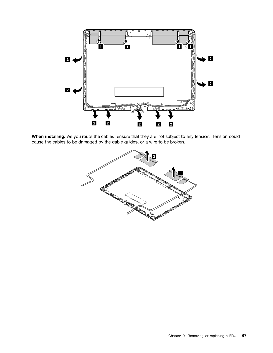
When installing
Removal steps of wireless antenna assembly
Removing or replacing a FRU
Hardware Maintenance Manual
Appendix A. Notices
Trademarks
Electronic emissions notices
Page
1P0B48943