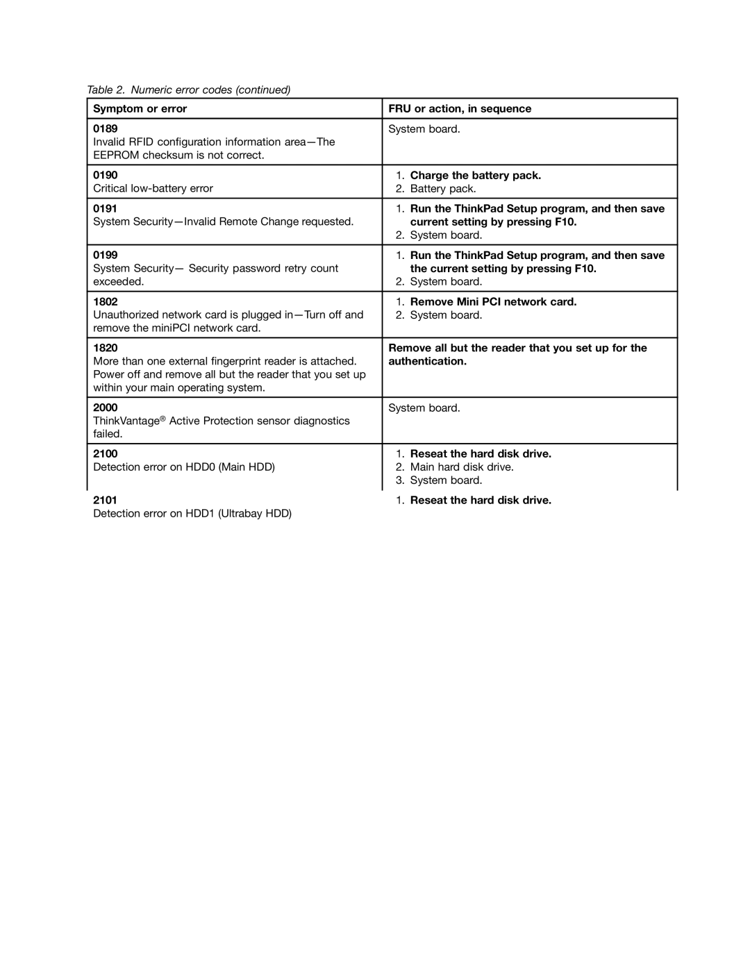
Hardware Maintenance Manual
ThinkPad S230u
First Edition September Copyright Lenovo
Contents
Appendix A. Notices
ThinkPad S230u Machine Type
About this manual
iv Hardware Maintenance Manual
General safety
Chapter 1. Safety information
Electrical safety
Handling devices that are sensitive to electrostatic discharge
Safety inspection guide
Grounding requirements
Safety notices multilingual translations
DANGER
DANGER DANGER DANGER DANGER DANGER DANGER
Chapter 1. Safety information
DANGER
6 Hardware Maintenance Manual
Chapter 1. Safety information
PERIGO PERIGO PERIGO PERIGO PERIGO PERIGO
8 Hardware Maintenance Manual
PERIGO PERIGO DANGER DANGER DANGER
Chapter 1. Safety information
DANGER DANGER DANGER DANGER DANGER
10 Hardware Maintenance Manual
VORSICHT
VORSICHT VORSICHT VORSICHT VORSICHT
Chapter 1. Safety information
VORSICHT VORSICHT VORSICHT
12 Hardware Maintenance Manual
Chapter 1. Safety information
14 Hardware Maintenance Manual
Chapter 1. Safety information
16 Hardware Maintenance Manual
Chapter 1. Safety information
18 Hardware Maintenance Manual
Chapter 1. Safety information
20 Hardware Maintenance Manual
3. Select Drivers & Software
Chapter 2. Important service information
Strategy for replacing FRUs
Before replacing parts
Dynamic Configure To Order CTO
How to use error message
Important notice for replacing a system board
Strategy for replacing FRUs for CTO, CMV, and GAV Product definition
2. Click Warranty & Services 3. Click Check Warranty Status
FRU identification for CTO, CMV, and GAV products
Using PEW
Using eSupport
4. Click Product & Parts Detail
2. Click Parts & Accessories
What to do first
Chapter 3. General checkout
The following are not covered under warranty
Lenovo Solution Center
Checkout guide
Quick test programs
Bootable diagnostic programs
UEFI diagnostic program
Checking the ac power adapter
Power system checkout
2. Click Lenovo Bootable Diagnostics
Checking the backup battery
Checking the battery pack
Checking operational charging
30 Hardware Maintenance Manual
If the voltage is not correct, replace the backup battery
Operating System Recovery Disc one disc
Chapter 4. Related service information
Restoring the factory contents by using Recovery Disc Set
Service Web site
Restoring the computer to factory default settings
Using the Windows recovery programs on the Windows 8 operating system
2. Insert the Operating System Recovery Disc into the DVD drive
Change PC settings General
Passwords
Power-on password
Hard-disk password
6. Select Power-On Password
Supervisor password
How to remove the power-on password
How to remove the hard-disk password
6. Select Master HDP
Power management
Sleep mode
Hibernation mode
Symptom-to-FRU index
Wireless off mode
Numeric error codes
current setting by pressing F10
Symptom or error
Charge the battery pack
Run the ThinkPad Setup program, and then save
Symptom or error beeps, if any
Error messages
No-beep symptoms
Beep symptoms
Intermittent problems
LCD-related symptoms
Undetermined problems
1. Turn off the computer
Indicator
Chapter 5. Status indicators
Meaning
Meaning
Indicator
Special key
Chapter 6. Special keys
Description
Description
Special key
Press this key to view the programs that you have opened
Chapter 7. Locations
Locating computer controls, connectors, and indicators
Front view
This topic introduces the following service parts
Rear view
Bottom view
Locating FRUs and CRUs
CRU statement for customers
48 Hardware Maintenance Manual
Major FRUs and CRUs
Self-service CRU
Optional-service
Optional-service
Self-service CRU
Description
50 Hardware Maintenance Manual
LCD FRUs
Self-service CRU
Optional-service
Description
Looking up FRU information
Self-service CRU
Optional-service
52 Hardware Maintenance Manual
Logic card to plastic
Chapter 8. FRU replacement notices
Screw notices
Plastic to plastic
Restoring the serial number of the system unit
Retaining serial numbers
MTM on rear label
Reading or writing the ECA information
Retaining the UUID
Product ID on rear label
56 Hardware Maintenance Manual
General guidelines
Chapter 9. Removing or replacing a FRU
DANGER
1010 Hard disk drive or solid-state drive
Disabling the built-in battery
Before servicing the computer
Removing the SIM card
Chapter 9. Removing or replacing a FRU
Removal steps of hard disk drive or solid-state drive bracket
Step
1020 Keyboard
60 Hardware Maintenance Manual
Removal steps of keyboard
Chapter 9. Removing or replacing a FRU
When installing
1030 PCI Express Mini Card for wireless LAN
Removal steps of PCI Express Mini Card for wireless LAN
Screw quantity
Removal steps of PCI Express Mini Card for wireless WAN
64 Hardware Maintenance Manual
Step
Chapter 9. Removing or replacing a FRU
Removal steps of mSATA solid-state drive
Screw quantity
1050 Keyboard bezel, backup battery, and speaker assembly
Removal steps of keyboard bezel
Step
Color
When installing
Step
Screw quantity
Rotate the LCD unit in the direction shown by the arrow
68 Hardware Maintenance Manual
Step
1060 Battery pack
Removal step of backup battery DANGER
Removal steps of speaker assembly
Step
1070 Proximity sensors
Removal steps of battery pack DANGER
Important notices for replacing a battery pack
Color
Removal steps of proximity sensors
Step
Screw quantity
72 Hardware Maintenance Manual
Removal steps of thermal fan assembly
Removal steps of hard disk drive or solid-state drive connector
1090 LCD unit
Screw quantity
74 Hardware Maintenance Manual
Removal steps of LCD unit
Step
When installing
Color
76 Hardware Maintenance Manual
Step
Screw quantity
Removal steps of DC-in connector
1100 DC-in connector
Chapter 9. Removing or replacing a FRU
Removal steps of system board and base cover assembly
1110 System board and base cover assembly
Applying labels to the base cover
The following illustration shows the location of each label
2020 LCD panel
2010 Button bezel
Removal steps of button bezel
Step
2030 Button board
82 Hardware Maintenance Manual
Removal steps of LCD panel
Screw quantity
2040 Integrated camera
Removal steps of button board
Step
Removal steps of integrated camera
2050 Hinge
Removal steps of hinge
When you pull the cables through the hole in the hinge, rout the cables as shown in the following illustration
When installing
86 Hardware Maintenance Manual
Removal steps of wireless antenna assembly
Chapter 9. Removing or replacing a FRU
88 Hardware Maintenance Manual
Note Some models might not have the wireless WAN antennas
Lenovo United States, Inc 1009 Think Place - Building One
Appendix A. Notices
Morrisville, NC U.S.A Attention Lenovo Director of Licensing
Trademarks
Electronic emissions notices
Page
Part Number 0B48943 Printed in 1P P/N 0B48943
1P0B48943