Room Air Conditioner
Table of Contents
Install the panel and the cover
Safety Precautions
Installation
Do not use damaged power cords, plugs, or a loose socket
Operation
Do not install the product on a defective installation stand
Sounds, odors, or smoke comes
When flammable gas leaks, turn
Do not place a heater or other
Do not use the product in a tight
That water is drained away prop
Keep level even when installing
Ing foods, works of art, etc. It is a
Product when removing
Do not use the product for spe
Cial purposes, such as preserv
It is not sanitary and could cause
Disuse
Outlet while the air conditioner is
Indoor Unit
Dimensions
Symbols Used in this Manual
9k, 12k Models
Outdoor Unit
Models
Product Specifications
Installation Tools
Installation
Installation Parts
Installation Map
This Product Contains R-410A Refrigerant
Confirm The Refrigerant
Outdoor unit
Rooftop Installations
Select the best Location
Indoor unit
Piping Length and Elevation
Oil trap should be installed every 16.4~23feets 5~7 meters
Drain hose junction
Preparing Work for Installation
Open panel front
Cover pipe and cover side remove
Case of nothing wrong, connect
Pipe and the wire. Refer to installation
Fixing Indoor Unit
Flaring Work
Flaring work and connection of piping
Foamed polyethylene or equivalent is recommended
Connecting the Piping
Check
Indoor
Indoor unit tubing Flare nut Pipings
Wrap the insulation material around the connecting portion
Bad case
For right piping. Follow the instruction below Good case
Connection of Piping -Outdoor
Connecting the Cables
How to connect wiring to the terminals
Connection method of the connecting cableExample
Connecting the cable between indoor unit and outdoor unit
Drain piping
Checking the Drainage
To check the drainage
Forming the Piping
Air purging with vacuum pump
Air Purging
Air purging
Finishing the job
Soap water method
Evacuation
Charging
Panel Front Assembly
Evaluation of the performance
Prepare remote controller
Test Running
Settlement of outdoor unit
Pump Down
Pump Down Procedure
How to replace picture & photograph
Functions
Operation
Function of main control
Time delay Safety Control
Chaos Swing Mode
Cooling Operation Mode
Auto Operation for Cooling
Auto Operation Electronic control mode
Auto Operation for Heatingonly Heating Model
Healthy Dehumidification
Auto Operation for Dehumidificationonly Heating Model
Hot-Start Control
Heating Operation Modeonly Heating Model
Heating Mode with the Sleep Modeonly Heating Model
Cooling or Heating Mode with Sleep Mode Auto Control
Cooling Mode with the Sleep Mode
Test operation
Auto restart
Forced Operation
Cooling Heat pump Model
Operation Indication Lamps
Signal Receptor
Display Function
Self-diagnosis Function
Nd F Button
Remote Control Operations
Controls
To remove the Control Box
Disassembly
To remove the Grille from the Chassis
To remove the Motor
To remove the Evaporator. Remove hole tubing holde
Before removing the Turbo Fan
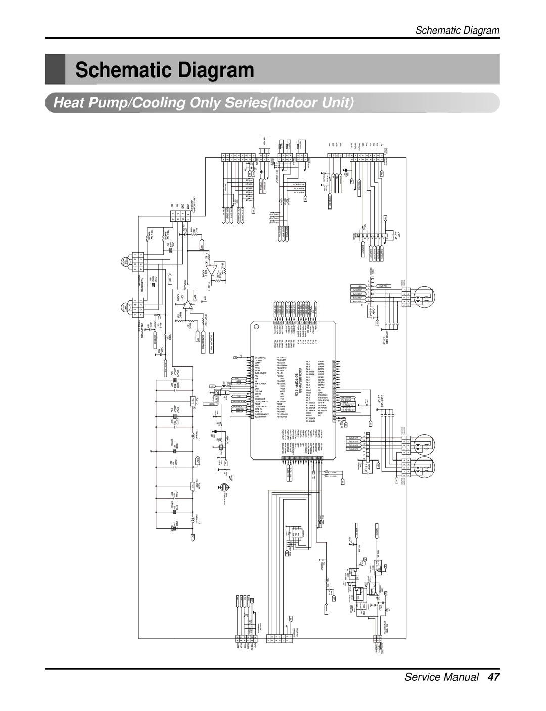
Heat Pump/Cooling Only SeriesIndoor Unit
Schematic Diagram
Heat Pump Series/ Cooling Only Series Outdoor Unit
No A20999A PCB ASSEMBLY, Main Top View Bottom View
Indoor Unit P.W.B. Assembly
No A20901C PCB ASSEMBLY, Main Top View Bottom View
Outdoor Unit P.W.B. Assembly
Display P.W.B. ASM
No A20921A PCB Assembly
Wiring Diagram
Outdoor UnitCooling Only Models, & Heating Models
Refrigeration Cycle Diagram
Troubleshooting Guide
Piping Length and Elevation
Air purging of the charge hose
Procedure
Way Valve
Pumping Down
Re-air purging
Gas leakage
Balance refrigerant of the 3-way valve
All amount of refrigerant leaked
Evacuation
Purge the air from the charge hose
Gas Charging
After Evacuation
Connect the charge hose to the charging cylinder
Additional gas charging
Method of using graph
Method of using equation
According to Indoor & Outdoor Temperature
Trouble analysis
Cycle Parts
Product does not operate at all
Electronic Parts 9k model
Product is not operate with the remote controller
Compressor/Outdoor Fan are unable to drive
Nector
When indoor Fan does not operate
When Vertical Louver does not operate
When a comunication error occurs
Indoor Unit
Phenomena in case of connecting error
Outdoor Unit
RY-COMP-B
Voltage of Connectors according to Indoor Fan Speed
Indoor Unit
Exploded View
Outdoor Unit
Parts ListIndoor
Replacement Parts List
Parts ListOutdoor
December No A20926C

 Heat Pump/Cooling Only Series(Indoor Unit)