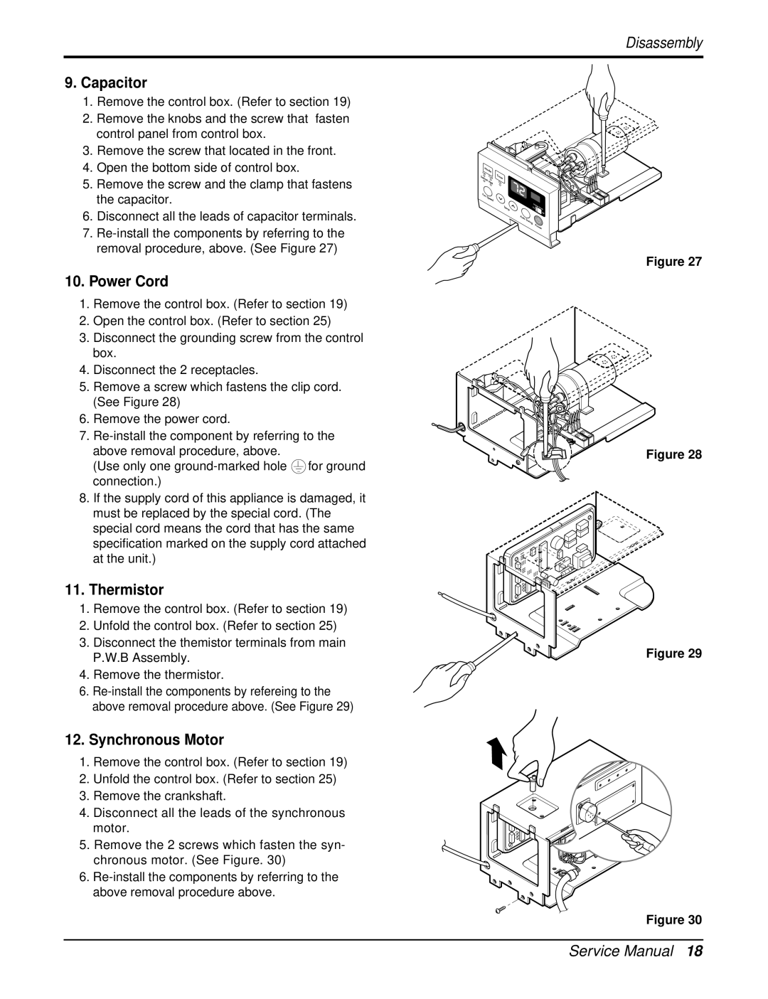
9.Capacitor
1.Remove the control box. (Refer to section 19)
2.Remove the knobs and the screw that fasten control panel from control box.
3.Remove the screw that located in the front.
4.Open the bottom side of control box.
5.Remove the screw and the clamp that fastens the capacitor.
6.Disconnect all the leads of capacitor terminals.
7.
10.Power Cord
1.Remove the control box. (Refer to section 19)
2.Open the control box. (Refer to section 25)
3.Disconnect the grounding screw from the control box.
4.Disconnect the 2 receptacles.
5.Remove a screw which fastens the clip cord. (See Figure 28)
6.Remove the power cord.
7.
above removal procedure, above.
(Use only one ![]() for ground connection.)
for ground connection.)
8.If the supply cord of this appliance is damaged, it must be replaced by the special cord. (The special cord means the cord that has the same specification marked on the supply cord attached at the unit.)
11.Thermistor
1.Remove the control box. (Refer to section 19)
2.Unfold the control box. (Refer to section 25)
3.Disconnect the themistor terminals from main P.W.B Assembly.
4.Remove the thermistor.
6.
12.Synchronous Motor
1.Remove the control box. (Refer to section 19)
2.Unfold the control box. (Refer to section 25)
3.Remove the crankshaft.
4.Disconnect all the leads of the synchronous motor.
5.Remove the 2 screws which fasten the syn- chronous motor. (See Figure. 30)
6.
Disassembly
Figure 27
Figure 28
Figure 29
Figure 30
Service Manual 18