Installation

4.0 INSTALLATION

! WARNING

Dangerous voltages exist in power distribution units and power conditioning units. To ensure maximum safety, all circuits breakers in the panelboard should be removed of power and the input feeder breaker should be turned off and locked-out in accordance with NEC and local/ state code.

NOTE

Installation of Liebert LDM components or other monitoring devices should be performed by qualified personnel only.

This section provides instructions for installing and connecting Liebert LDM current transformers. If service needs to be performed on any Liebert LDM component, contact Emerson Network Power Lie- bert Services at 1-800-LIEBERT (1-800-543-2378) for assistance.

4.1Installing a BSM (CT Module Assembly)

In most cases the BSM—the CT Module—is factory-installed and no further work is required. If you need to add a CT Module, it attaches easily to the side of a panelboard to monitor any combination of 1-, 2- and 3-pole circuit breakers.

For side-by-side panelboards (21 circuits on each side), attach one CT Module to each side of the panelboard, ensuring that the center of the CT hole lines up to the branch circuit breaker connection.

For SqD Inline panelboards (42 circuits in a row), the two CT Mod- ules must be interlocked to monitor 42 inline circuits. Flip the second, lower CT Module so that the two cutout sections line up, then attach the screws to secure the CT Modules to the panelboard.

For GE Inline type panelboards, the two CT Modules fit end to end. Flip the second, lower CT Module so that the 50-pin ribbon cable con- nector, mounted on the bottom of the CT Module, lines up with the hole in the panelboard mounting bracket.

Install the circuit breakers according to the manufacturer’s documentation. Route the circuit wire through the center of the CT and attach securely to the circuit breaker.

4.1.1Connecting Panelboards A and B

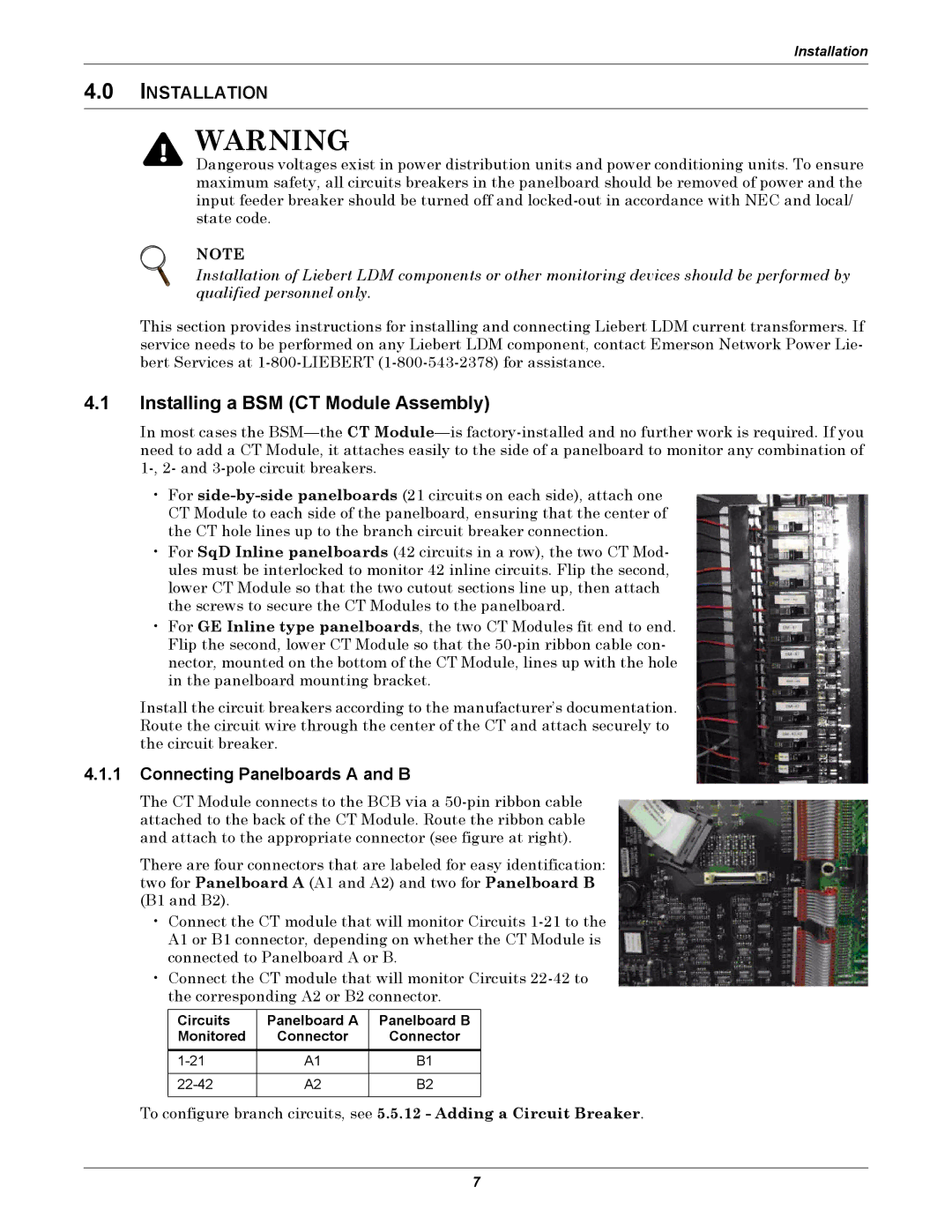
The CT Module connects to the BCB via a 50-pin ribbon cable attached to the back of the CT Module. Route the ribbon cable and attach to the appropriate connector (see figure at right).

There are four connectors that are labeled for easy identification: two for Panelboard A (A1 and A2) and two for Panelboard B (B1 and B2).

Connect the CT module that will monitor Circuits 1-21 to the A1 or B1 connector, depending on whether the CT Module is connected to Panelboard A or B.

Connect the CT module that will monitor Circuits 22-42 to the corresponding A2 or B2 connector.

Circuits

Panelboard A

Panelboard B

Monitored

Connector

Connector


1-21

A1

B1


22-42

A2

B2


To configure branch circuits, see 5.5.12 - Adding a Circuit Breaker.

7

Page 11
Image 11
Liebert LDM user manual Installing a BSM CT Module Assembly, Installation, Connecting Panelboards a and B

LDM specifications

Liebert LDM (Liebert Digital Monitor) is an advanced thermal management solution, specifically designed to enhance the performance and reliability of critical infrastructure systems. This innovative product from Vertiv caters to the growing demand for efficient cooling solutions in data centers, telecommunication sites, and other facilities requiring precise environmental control.

One of the standout features of the Liebert LDM is its advanced monitoring capabilities. The device is equipped with numerous sensors that measure crucial parameters, including temperature, humidity, and airflow. These measurements help operators analyze the cooling efficiency of their systems and ensure optimal operating conditions. The real-time data provided by the Liebert LDM allows for proactive maintenance, reducing the risk of equipment failure due to overheating or improper humidity levels.

The Liebert LDM employs sophisticated algorithms to optimize cooling performance. Its ability to analyze data trends plays a vital role in preventing hot spots and ensuring uniform cooling throughout the facility. This technology enhances the overall efficiency of cooling systems, which translates into reduced energy consumption and lower operating costs.

Another key characteristic of the Liebert LDM is its modular design. This flexibility allows users to scale their monitoring capabilities based on the size and complexity of their cooling setup. Whether a small server room or a large data center, the Liebert LDM can be tailored to meet specific operational needs.

Integration is another core advantage of the Liebert LDM. It seamlessly connects with various management systems and can be monitored through user-friendly interfaces. This interoperability ensures that facility managers can easily track performance metrics and integrate the Liebert LDM into their existing operational protocols.

The construction of the Liebert LDM is designed with durability and longevity in mind. Built to withstand the rigors of commercial use, the device features robust housing and weather-resistant components. This resilience ensures that the Liebert LDM remains a reliable tool within critical environments.

In summary, the Liebert LDM is a sophisticated thermal management solution combining precision monitoring, energy efficiency, modular flexibility, seamless integration, and robust design. As technology evolves, maintaining optimal environmental conditions becomes increasingly crucial. The Liebert LDM addresses these challenges, ensuring that critical systems operate reliably and efficiently in the face of rising demands.