Liebert XDV Component Locations and Model Number Nomenclature
1.0LIEBERT XDV COMPONENT LOCATIONS AND MODEL NUMBER NOMENCLATURE
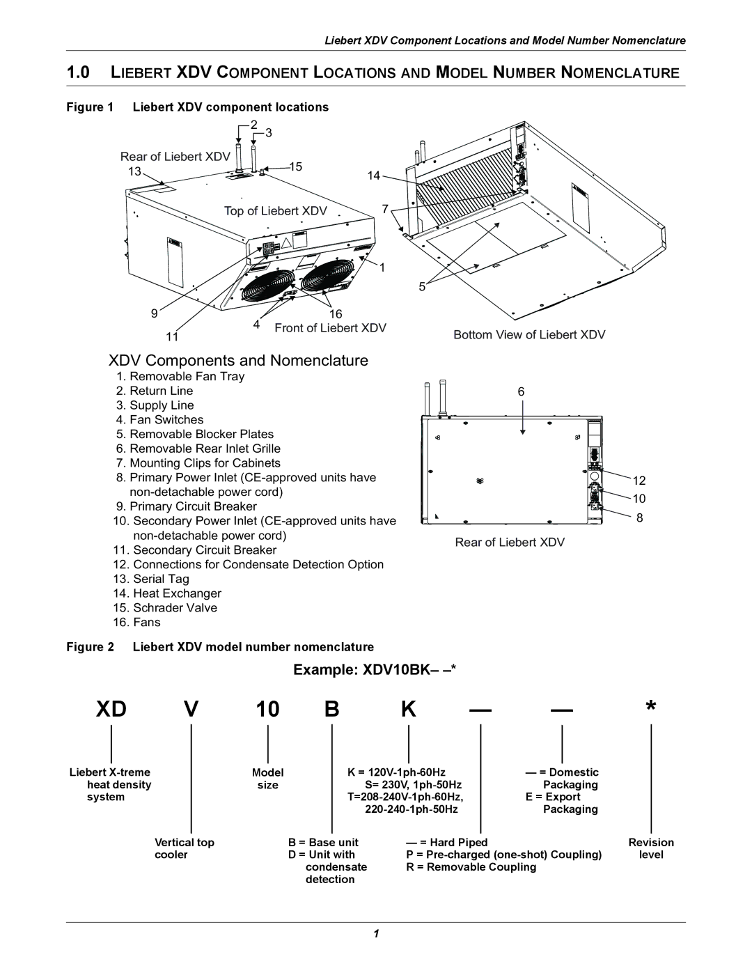
Figure 1 Liebert XDV component locations
2 | 3 |
|
|
Rear of Liebert XDV | 15 |
|
|
13 | 14 |
| |
|
| ||
|
|
| |
Top of Liebert XDV | 7 |
| |
|
| 1 |
|
|
|
| 5 |
9 |
| 16 |
|
4 | Front of Liebert XDV | Bottom View of Liebert XDV | |
11 |
|
| |
XDV Components and Nomenclature
1.Removable Fan Tray
2.Return Line
3.Supply Line
4.Fan Switches
5.Removable Blocker Plates
6.Removable Rear Inlet Grille
7.Mounting Clips for Cabinets
8.Primary Power Inlet
9.Primary Circuit Breaker
10.Secondary Power Inlet
11.Secondary Circuit Breaker
12.Connections for Condensate Detection Option
13.Serial Tag
14.Heat Exchanger
15.Schrader Valve
16.Fans
6
Rear of Liebert XDV
12
![]()
![]()
![]() 10
10 ![]() 8
8
Figure 2 Liebert XDV model number nomenclature
Example: XDV10BK– –*
XD | V | 10 | B |
| K | — | — | * | ||||||||
|
|
|
|
|
|
|
|
|
|
|
|
|
|
| ||
Liebert |
|
| Model |
| K = |
|
| — = Domestic |
|
| ||||||
heat density |
|
| size |
|
| S= 230V, |
|
| Packaging |
|
| |||||
system |
|
|
|
|
|
|
| E = Export |
|
| ||||||
|
|
|
|
|
|
|
|
|
| Packaging |
|
| ||||
|
|
|
|
|
|
|
|
|
|
|
|
|
|
|
| |
|
| Vertical top |
|
| B = Base unit |
| — = Hard Piped |
|
| Revision | ||||||
|
| cooler |
|
| D = Unit with |
| P = | level | ||||||||
|
|
|
|
|
| condensate | R = Removable Coupling |
|
| |||||||
|
|
|
|
|
| detection |
|
|
|
|
|
|
|
|
| |
1