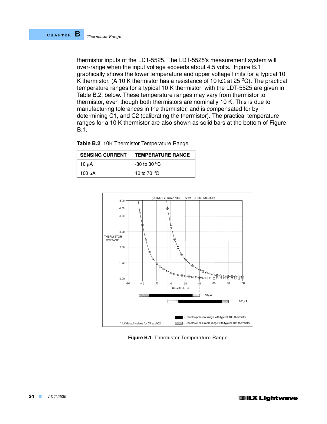
thermistor inputs of the LDT-5525. The LDT-5525's measurement system will over-range when the input voltage exceeds about 4.5 volts. Figure B.1 graphically shows the lower temperature and upper voltage limits for a typical 10 K thermistor. (A 10 K thermistor has a resistance of 10 kΩ at 25 oC). The practical temperature ranges for a typical 10 K thermistor with the LDT-5525 are given in Table B.2, below. These temperature ranges may vary from thermistor to thermistor, even though both thermistors are nominally 10 K. This is due to manufacturing tolerances in the thermistor, and is compensated for by determining C1, and C2 (calibrating the thermistor). The practical temperature ranges for a 10 K thermistor are also shown as solid bars at the bottom of Figure B.1.
Table B.2 10K Thermistor Temperature Range | | | | |
SENSING CURRENT | TEMPERATURE RANGE | | | | |
10 µA | -30 to 30 oC | | | | | | |
100 µA | 10 to 70 oC | | | | | | |
| | (USING TYPICAL* 10 Ωk | o | C THERMISTOR) | | |
5.00 | | @ 25 | | |
| | | | | | | |
4.50 | | | | | | | | |
4.00 | | | | | | | | |
3.00 | | | | | | | | |
THERMISTOR | | | | | | | | |
VOLTAGE | | | | | | | | |
2.00 | | | | | | | | |
1.00 | | | | | | | | |
0.00 | | | | | | | | |
-60 | -40 | -20 | 0 | 20 | 40 | 60 | 80 | 100 |
| | | DEGREES C | | | | |
| | | | | | 10µ A | | |
| | | | | | | | 100 µ A |
| | | | - Denotes practical range with typical 10K thermistor |
* ILX default values for C1 and C2 | | - Denotes measurable range with typical 10K thermistor |
Figure B.1 Thermistor Temperature Range | |
34 LDT-5525