GAS PURGE
STD
LOCK
SPOT
4 - Step Trigger Mode Selection
Pressing both the Gas Purge key and then the Trigger mode select key while the
(See Mode Selection and Display Control Keys sections).
![]() WARNING
WARNING
Check to be sure the Retaining Spring has fully returned to the locking position and has SECURELY locked the
___________________________________________
7)To remove
To Mount 10 to 44 lb (4.5-20kg) Spool (12”/300mm Diameter):
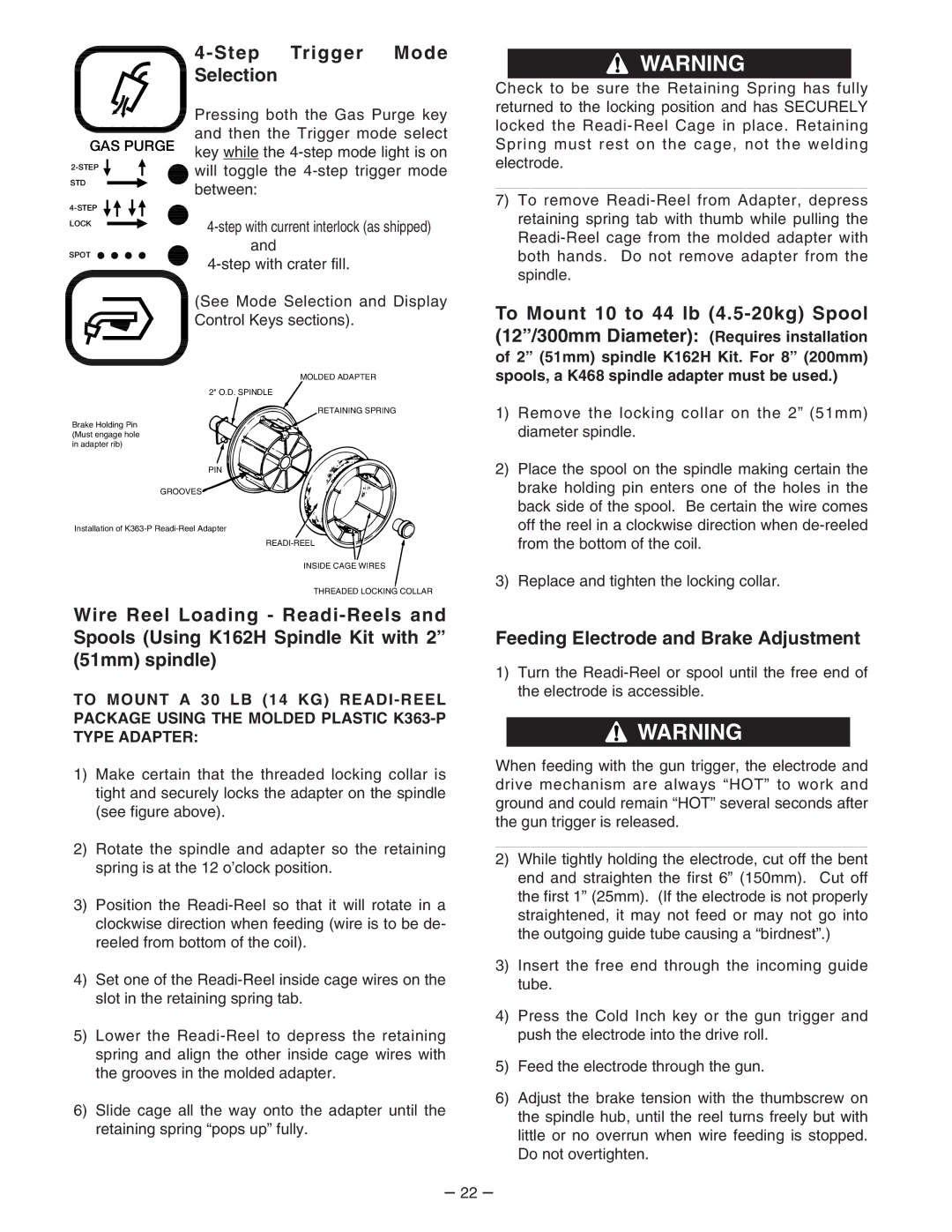
MOLDED ADAPTER
2" O.D. SPINDLE
RETAINING SPRING
Brake Holding Pin (Must engage hole in adapter rib)
PIN
GROOVES
Installation of
INSIDE CAGE WIRES
THREADED LOCKING COLLAR
Wire Reel Loading -
TO MOUNT A 30 LB (14 KG) READI - REEL PACKAGE USING THE MOLDED PLASTIC
1)Make certain that the threaded locking collar is tight and securely locks the adapter on the spindle (see figure above).
2)Rotate the spindle and adapter so the retaining spring is at the 12 o’clock position.
3)Position the
4)Set one of the
5)Lower the
6)Slide cage all the way onto the adapter until the retaining spring “pops up” fully.
of 2” (51mm) spindle K162H Kit. For 8” (200mm) spools, a K468 spindle adapter must be used.)
1)Remove the locking collar on the 2” (51mm) diameter spindle.
2)Place the spool on the spindle making certain the brake holding pin enters one of the holes in the back side of the spool. Be certain the wire comes off the reel in a clockwise direction when
3)Replace and tighten the locking collar.
Feeding Electrode and Brake Adjustment
1)Turn the
![]() WARNING
WARNING
When feeding with the gun trigger, the electrode and drive mechanism are always “HOT” to work and ground and could remain “HOT” several seconds after the gun trigger is released.
___________________________________________
2)While tightly holding the electrode, cut off the bent end and straighten the first 6” (150mm). Cut off the first 1” (25mm). (If the electrode is not properly straightened, it may not feed or may not go into the outgoing guide tube causing a “birdnest”.)
3)Insert the free end through the incoming guide tube.
4)Press the Cold Inch key or the gun trigger and push the electrode into the drive roll.
5)Feed the electrode through the gun.
6)Adjust the brake tension with the thumbscrew on the spindle hub, until the reel turns freely but with little or no overrun when wire feeding is stopped. Do not overtighten.
– 22 –