TROUBLESHOOTING | ||
|
|
|
| Observe all Safety Guidelines detailed throughout this manual |
|
|
|
|
PROBLEMS
(SYMPTOMS)
POSSIBLE AREAS OF MISADJUSTMENTS(S)
RECOMMENDED
COURSE OF ACTION
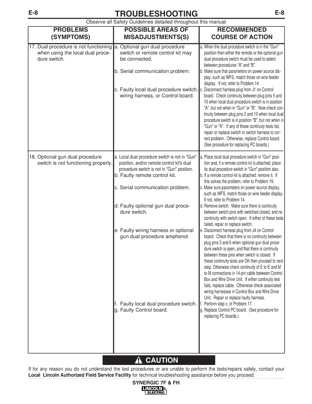
17. Dual procedure is not functioning | a. Optional gun dual procedure | a. When the dual procedure switch is in the “Gun” | |
when using the local dual proce- | switch or remote control kit may | position then either the remote or the optional gun | |
dure switch. | be connected. | dual procedure switch must be used to select | |
|
| between procedures “A” and “B”. | |
| b. Serial communication problem. | b. Make sure that parameters on power source dis- | |
|
| play, such as WFS, match those on wire feeder | |
|
| display. If not, refer to Problem 14. | |
| c. Faulty local dual procedure switch, | c. Disconnect harness plug from J1 on Control | |
| wiring harness, or Control board. | board. Check continuity between plug pins 5 and | |
|
| 10 when local dual procedure switch is in position | |
|
| "A", but not when in "Gun" or "B". Now check con- | |
|
| tinuity between plug pins 3 and 10 when local dual | |
|
| procedure switch is in position "B", but not when in | |
|
| "Gun" or "A". If any of these continuity tests fail, | |
|
| repair or replace switch or switch harness to cor- | |
|
| rect problem. Otherwise, replace Control board. | |
|
| (See procedure for replacing PC boards.) | |
|
|
|
|
18. Optional gun dual procedure | a. Local dual procedure switch is not in "Gun" | a. Place local dual procedure switch in "Gun" posi- | |
switch is not functioning properly. | position, and/or remote control kit's dual | tion and, if a remote control kit is attached, place | |
| procedure switch is not in "Gun" position. | its dual procedure switch in "Gun" position also. | |
| b. Faulty remote control kit. | b. If a remote control kit is attached, remove it. If | |
|
| this solves the problem, refer to Problem 19. | |
| c. Serial communication problem. | c. Make sure parameters on power source display, | |
|
| such as WFS, match those on wire feeder display. | |
|
| If not, refer to Problem 14. | |
| d. Faulty optional gun dual proce- | d. Remove switch. Make sure there is continuity | |
| dure switch. | between switch pins with switched closed, and no | |
|
| continuity with switch open. If either of these tests | |
|
| failed, repair or replace switch. | |
| e. Faulty wiring harness or optional | e. Disconnect harness plug from J4 on Control | |
| gun dual procedure amphenol. | board. Check that there is no continuity between | |
|
| plug pins 3 and 6 when optional gun dual proce- | |
|
| dure switch is open, and that there is continuity | |
|
| between these pins when switch is closed. If | |
|
| these continuity tests are OK then proceed to next | |
|
| step. Otherwise check continuity of E to E and M | |
|
| to M connections in | |
|
| Box and Wire Drive Unit. If either continuity test | |
|
| fails, replace cable. Otherwise check associated | |
|
| wiring harnesses in Control Box and Wire Drive | |
|
| Unit. Repair or replace faulty harness. | |
| f. Faulty local dual procedure switch. | f. Perform step c. of Problem 17. | |
| g. Faulty Control board. | g. Replace Control PC board. (See procedure for | |
|
| replacing PC boards.) | |
|
|
|
|
![]() CAUTION
CAUTION
If for any reason you do not understand the test procedures or are unable to perform the tests/repairs safely, contact your Local Lincoln Authorized Field Service Facility for technical troubleshooting assistance before you proceed.
SYNERGIC 7F & FH
