TROUBLESHOOTING | ||
|
|
|
| Observe all Safety Guidelines detailed throughout this manual |
|
|
|
|
PROBLEMS
(SYMPTOMS)
POSSIBLE AREAS OF MISADJUSTMENTS(S)
RECOMMENDED
COURSE OF ACTION
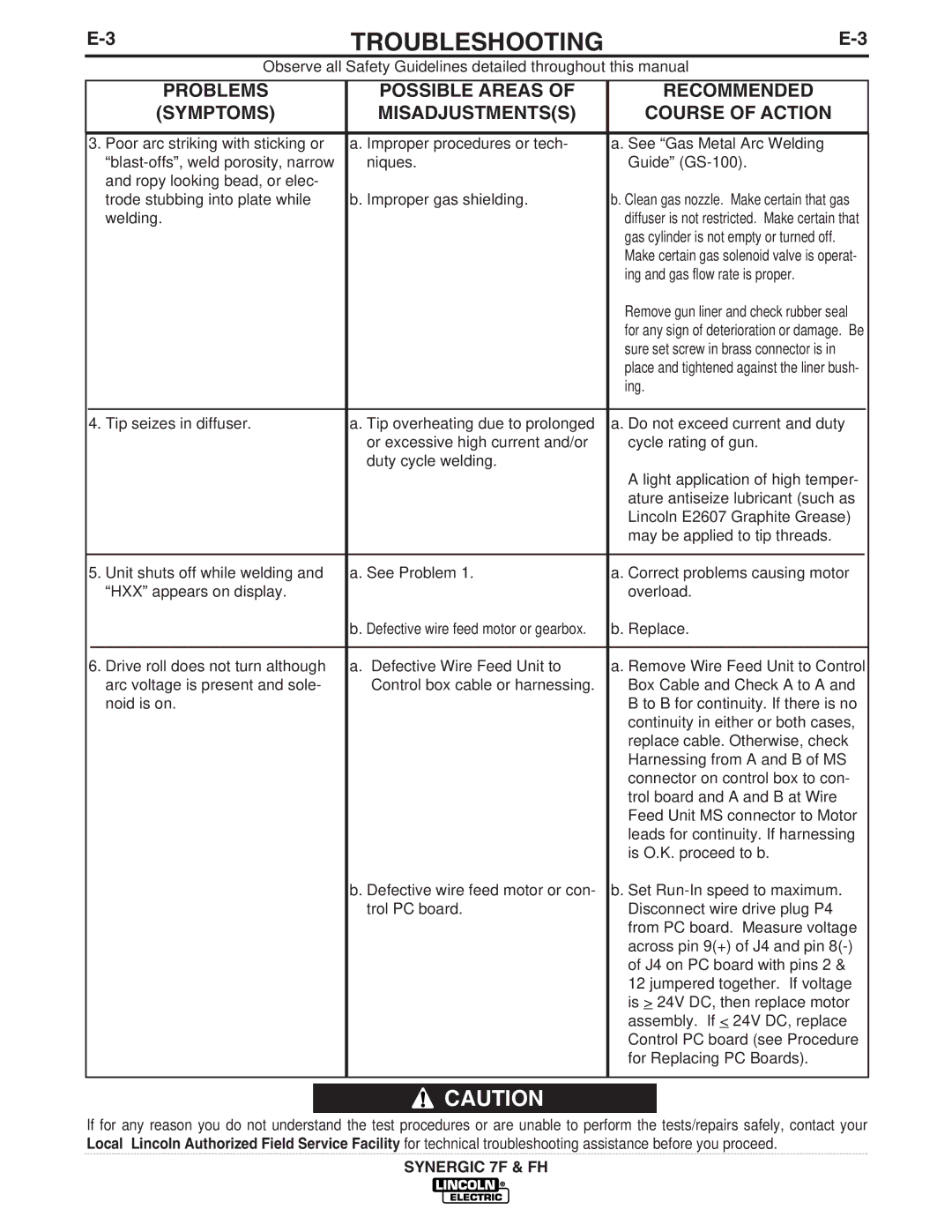
3. Poor arc striking with sticking or | a. Improper procedures or tech- | a. See “Gas Metal Arc Welding | |||
| niques. | Guide” | |||
| and ropy looking bead, or elec- |
|
|
|
|
| trode stubbing into plate while | b. Improper gas shielding. | b. Clean gas nozzle. Make certain that gas | ||
| welding. |
| diffuser is not restricted. Make certain that | ||
|
|
| gas cylinder is not empty or turned off. | ||
|
|
| Make certain gas solenoid valve is operat- | ||
|
|
| ing and gas flow rate is proper. | ||
|
|
| Remove gun liner and check rubber seal | ||
|
|
| for any sign of deterioration or damage. Be | ||
|
|
| sure set screw in brass connector is in | ||
|
|
| place and tightened against the liner bush- | ||
|
|
| ing. | ||
|
|
|
|
|
|
4. Tip seizes in diffuser. | a. Tip overheating due to prolonged | a. Do not exceed current and duty | |||
|
| or excessive high current and/or | cycle rating of gun. | ||
|
| duty cycle welding. |
|
|
|
|
|
| A light application of high temper- | ||
|
|
| ature antiseize lubricant (such as | ||
|
|
| Lincoln E2607 Graphite Grease) | ||
|
|
| may be applied to tip threads. | ||
|
|
|
|
| |
5. Unit shuts off while welding and | a. See Problem 1. | a. Correct problems causing motor | |||
| “HXX” appears on display. |
| overload. | ||
|
| b. Defective wire feed motor or gearbox. | b. Replace. | ||
|
|
|
| ||
6. Drive roll does not turn although | a. Defective Wire Feed Unit to | a. Remove Wire Feed Unit to Control | |||
| arc voltage is present and sole- | Control box cable or harnessing. | Box Cable and Check A to A and | ||
| noid is on. |
| B to B for continuity. If there is no | ||
|
|
| continuity in either or both cases, | ||
|
|
| replace cable. Otherwise, check | ||
|
|
| Harnessing from A and B of MS | ||
|
|
| connector on control box to con- | ||
|
|
| trol board and A and B at Wire | ||
|
|
| Feed Unit MS connector to Motor | ||
|
|
| leads for continuity. If harnessing | ||
|
|
| is O.K. proceed to b. | ||
|
| b. Defective wire feed motor or con- | b. Set | ||
|
| trol PC board. | Disconnect wire drive plug P4 | ||
|
|
| from PC board. Measure voltage | ||
|
|
| across pin 9(+) of J4 and pin | ||
|
|
| of J4 on PC board with pins 2 & | ||
|
|
| 12 jumpered together. If voltage | ||
|
|
| is > 24V DC, then replace motor | ||
|
|
| assembly. If < 24V DC, replace | ||
|
|
| Control PC board (see Procedure | ||
|
|
| for Replacing PC Boards). | ||
|
|
|
|
|
|
![]() CAUTION
CAUTION
If for any reason you do not understand the test procedures or are unable to perform the tests/repairs safely, contact your Local Lincoln Authorized Field Service Facility for technical troubleshooting assistance before you proceed.
SYNERGIC 7F & FH
