INSTALLATION | ||
|
|
|
SAFETY PRECAUTIONS
ELECTRIC SHOCK can kill.
•Only qualified personnel should per- form this installation.
•Turn off the input power to the power source at the disconnect switch or fuse box before working on this equipment. Turn off the input power to any other equipment connected to the welding system at the disconnect switch or fuse box before work- ing on this equipment.
•Do not touch electrically hot parts.
•Always connect the Power Wave grounding lug (located inside the reconnect input access door) to a proper safety (Earth) ground.
MOUNTING THE WIRE DRIVE UNIT
BOOM MOUNTING OF WIRE DRIVE UNIT
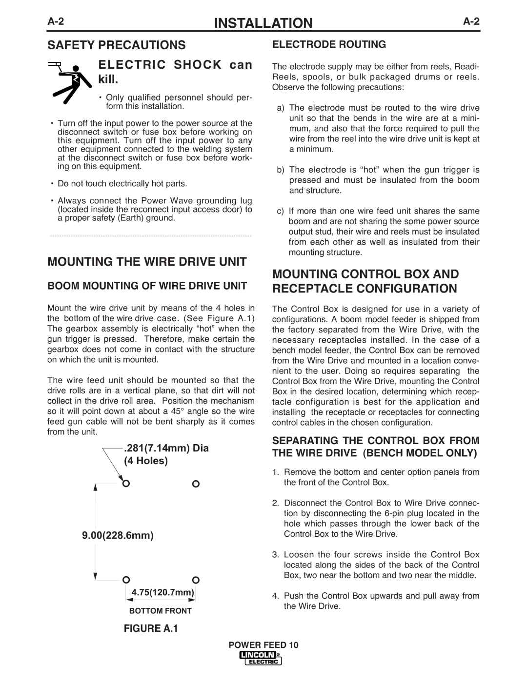
Mount the wire drive unit by means of the 4 holes in the bottom of the wire drive case. (See Figure A.1) The gearbox assembly is electrically “hot” when the gun trigger is pressed. Therefore, make certain the gearbox does not come in contact with the structure on which the unit is mounted.
The wire feed unit should be mounted so that the drive rolls are in a vertical plane, so that dirt will not collect in the drive roll area. Position the mechanism so it will point down at about a 45° angle so the wire feed gun cable will not be bent sharply as it comes from the unit.
.281(7.14mm) Dia
(4 Holes)
9.00(228.6mm)
4.75(120.7mm)
BOTTOM FRONT
FIGURE A.1
ELECTRODE ROUTING
The electrode supply may be either from reels, Readi- Reels, spools, or bulk packaged drums or reels. Observe the following precautions:
a)The electrode must be routed to the wire drive unit so that the bends in the wire are at a mini- mum, and also that the force required to pull the wire from the reel into the wire drive unit is kept at a minimum.
b)The electrode is “hot” when the gun trigger is pressed and must be insulated from the boom and structure.
c)If more than one wire feed unit shares the same boom and are not sharing the some power source output stud, their wire and reels must be insulated from each other as well as insulated from their mounting structure.
MOUNTING CONTROL BOX AND RECEPTACLE CONFIGURATION
The Control Box is designed for use in a variety of configurations. A boom model feeder is shipped from the factory separated from the Wire Drive, with the necessary receptacles installed. In the case of a bench model feeder, the Control Box can be removed from the Wire Drive and mounted in a location conve- nient to the user. Doing so requires separating the Control Box from the Wire Drive, mounting the Control Box in the desired location, determining which recep- tacle configuration is best for the application and installing the receptacle or receptacles for connecting control cables in the chosen configuration.
SEPARATING THE CONTROL BOX FROM THE WIRE DRIVE (BENCH MODEL ONLY)
1.Remove the bottom and center option panels from the front of the Control Box.
2.Disconnect the Control Box to Wire Drive connec- tion by disconnecting the
3.Loosen the four screws inside the Control Box located along the sides of the back of the Control Box, two near the bottom and two near the middle.
4.Push the Control Box upwards and pull away from the Wire Drive.
POWER FEED 10