INSTALLATION | ||
|
|
|
Mounting Synergic 7F Wire Drive Unit
Mount the wire feed unit by means of the insulated mounting bracket attached to the bottom of the gearbox. Reference L9777 (included with Drive unit) to find the size and location of the mounting holes. The gearbox assembly is electrically “hot” when the gun trigger is pressed. Therefore, make cer- tain the gearbox does not come in contact with the structure on which the unit is mounted.
The wire feed unit should be mounted so that the drive rolls are in a vertical plane so dirt will not collect in the drive roll area. Position the mechanism so it will point down at about a 45° angle so the wire feed gun cable will not be bent sharply as it comes from the unit.
Note: The
Mounting the STT-10 Control Box (K1565-2) (Boom Model)
Mounting the
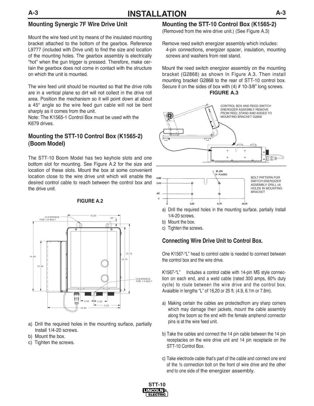
(Removed from the wire drive unit.) (See Figure A.3)
Remove reed switch energizer assembly which includes:
Mount the reed switch energizer assembly on the mounting bracket (G2868) as shown In Figure A.3. Then install mounting bracket G2868 to the rear of
FIGURE A.3
CONTROL BOX AND REED SWITCH
ENERGIZER ASSEMBLY REMOVE
FROM REEL STAND AND ADDED TO
MOUNTING BRACKET G2868
The
location of these slots. Mount the box at some convenient
location close to the wire drive unit which will enable the 2.62 ![]()
![]()
![]() desired control cable to reach between the control box and
desired control cable to reach between the control box and ![]()
![]()
![]()
![]()
![]()
![]()
![]()
![]()
![]()
the drive unit.
FIGURE A.2
BOLT PATTERN FOR SWITCH ENERGIZER ASSEMBLY, DRILL (4) HOLES IN MOUNTING BRACKET
CLEARANCE | 10.50 | |
.50 | ||
FOR 1/4 BOLT | ||
| ||
| 13.75 | |
14.00 |
| |
| 12.75 | |
10.00 |
| |
2.63 | 2.63 | |
| 5.25 | |
14.50 |
|
CLEARANCE FOR 1/4 BOLT
a)Drill the required holes in the mounting surface, partially Install
b)Mount the box.
c)Tighten the screws.
Connecting Wire Drive Unit to Control Box.
One
a) Making certain the cables are protectedfrom any sharp corners |
which may damage their jackets, mount the cable assembly |
along the boom so the end with the female amphenol connector |
pins is at the wire feed unit. |
a)Drill the required holes in the mounting surface, partially Install
b)Mount the box.
c)Tighten the screws.
b) Take the cables and connect the 14 pin cable between the 14 pin |
receptacles on the wire drive unit and 14 pin receptacle on the |
|
c) Take electrode cable thatʼs part of the cable and connect one end |
of the ½ connection bolt on the front of wire drive and the other |
end to one side of the energizer assembly. |