|
|
|
|
|
| INSTALLATION |
|
|
|
| ||||||||||
|
|
|
|
|
|
|
|
|
|
|
|
|
|
|
|
|
|
|
|
|
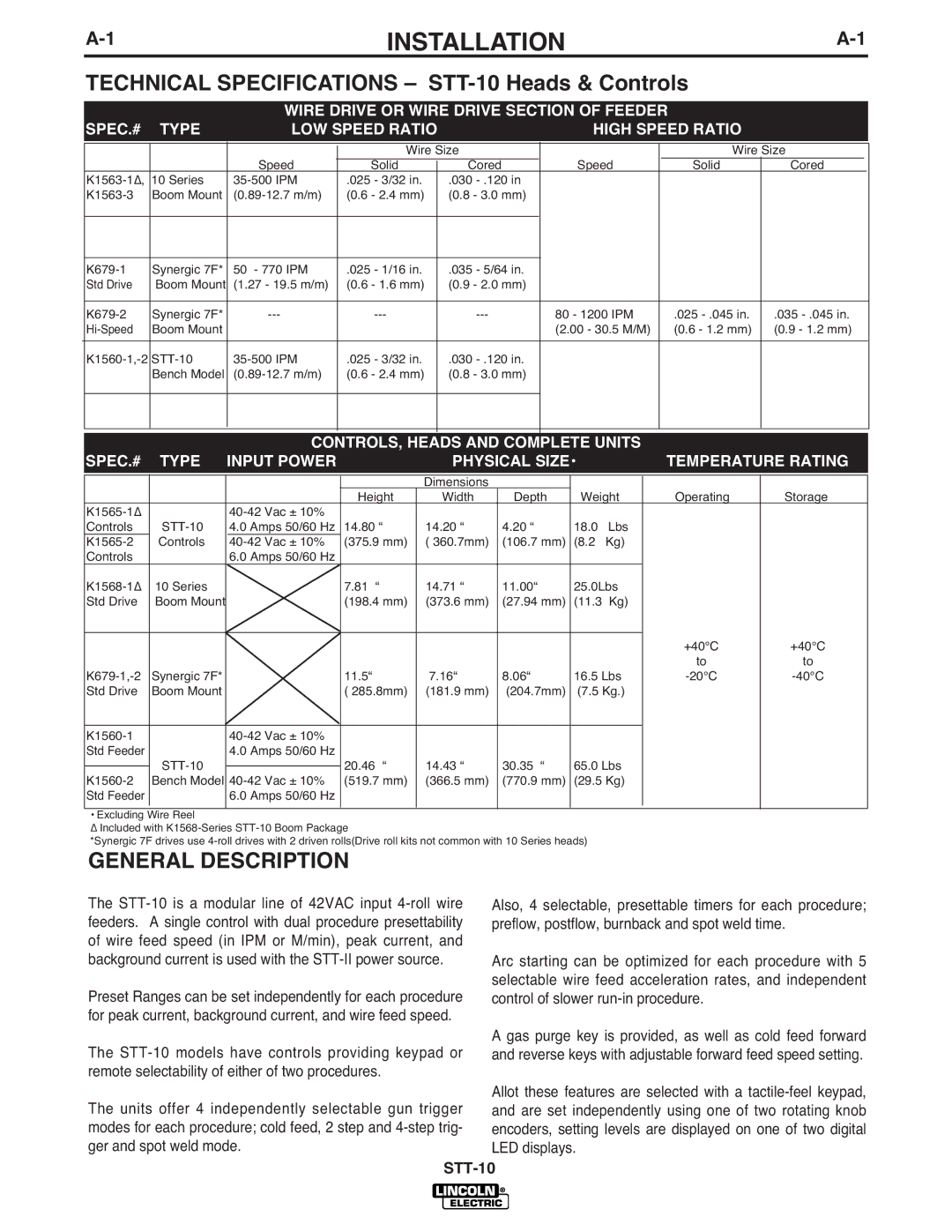
| TECHNICAL SPECIFICATIONS – |
|
| |||||||||||||||||
| SPEC.# | TYPE |
| WIRE DRIVE OR WIRE DRIVE SECTION OF FEEDER |
|
| ||||||||||||||
|
| LOW SPEED RATIO |
|
|
| HIGH SPEED RATIO |
|
| ||||||||||||
|
|
|
|
| Speed |
| Wire Size |
|
|
| Speed | Wire Size | ||||||||
|
|
|
|
|
|
|
|
| ||||||||||||
|
|
|
|
|
| Solid |
| Cored |
|
|
| Solid | Cored |
| ||||||
| 10 Series |
| .025 - 3/32 in. |
| .030 |
|
|
|
|
|
|
| ||||||||
| Boom Mount |
| (0.6 - 2.4 mm) |
| (0.8 - 3.0 mm) |
|
|
|
|
|
|
| ||||||||
|
|
|
|
|
|
|
|
|
|
|
|
|
|
|
|
|
| |||
|
|
|
|
|
|
|
|
|
|
|
|
|
|
|
|
|
| |||
| Synergic 7F* |
| 50 - 770 IPM | .025 - 1/16 in. |
| .035 - 5/64 in. |
|
|
|
|
|
|
| |||||||
| Std Drive | Boom Mount | (1.27 - 19.5 m/m) | (0.6 - 1.6 mm) |
| (0.9 - 2.0 mm) |
|
|
|
|
|
|
| |||||||
|
|
|
|
|
|
|
|
|
|
|
|
|
|
|
|
|
| |||
| Synergic 7F* |
|
|
|
|
|
|
| 80 - 1200 IPM | .025 | .035 | |||||||||
| Boom Mount |
|
|
|
|
|
|
|
|
|
| (2.00 - 30.5 M/M) | (0.6 - 1.2 mm) | (0.9 - 1.2 mm) | ||||||
|
|
|
|
|
|
|
|
|
|
|
|
|
|
|
|
| ||||
|
| .025 - 3/32 in. |
| .030 |
|
|
|
|
|
|
| |||||||||
|
|
| Bench Model |
| (0.6 - 2.4 mm) |
| (0.8 - 3.0 mm) |
|
|
|
|
|
|
| ||||||
|
|
|
|
|
|
|
|
|
|
|
|
|
|
|
|
|
| |||
|
|
|
|
|
|
|
|
|
|
|
|
|
|
|
|
|
|
|
|
|
|
|
|
|
|
|
|
|
|
|
|
|
|
|
|
|
|
|
|
|
|
| SPEC.# | TYPE |
| CONTROLS, HEADS AND COMPLETE UNITS | TEMPERATURE RATING | |||||||||||||||
| INPUT POWER |
|
|
| PHYSICAL SIZE• |
|
| |||||||||||||
|
|
|
|
|
|
|
|
|
|
|
|
|
|
|
|
|
|
| ||
|
|
|
|
|
|
|
| Dimensions |
|
|
|
|
|
|
|
|
| |||
|
|
|
|
|
|
| Height |
|
| Width |
| Depth | Weight |
| Operating | Storage | ||||
|
|
|
|
|
|
|
|
|
|
|
|
|
|
|
|
| ||||
| Controls |
| 4.0 Amps 50/60 Hz | 14.80 “ |
| 14.20 “ |
| 4.20 “ | 18.0 | Lbs |
|
|
|
| ||||||
| Controls |
| (375.9 mm) |
| ( 360.7mm) |
| (106.7 mm) | (8.2 | Kg) |
|
|
|
| |||||||
| Controls |
|
| 6.0 Amps 50/60 Hz |
|
|
|
|
|
|
|
|
|
|
|
|
|
| ||
| 10 Series |
|
|
| 7.81 “ |
| 14.71 “ |
| 11.00“ | 25.0Lbs |
|
|
|
| ||||||
| Std Drive | Boom Mount |
|
|
| (198.4 mm) |
| (373.6 mm) |
| (27.94 mm) | (11.3 Kg) |
|
|
|
| |||||
|
|
|
|
|
|
|
|
|
|
|
|
|
|
|
|
|
| +40°C | +40°C | |
|
|
|
|
|
|
|
|
|
|
|
|
|
|
|
|
|
| |||
|
|
|
|
|
|
|
|
|
|
|
|
|
|
|
|
|
| to | to | |
| Synergic 7F* |
|
|
| 11.5“ |
| 7.16“ |
| 8.06“ | 16.5 Lbs |
| |||||||||
| Std Drive | Boom Mount |
|
|
| ( 285.8mm) |
| (181.9 mm) |
| (204.7mm) | (7.5 Kg.) |
|
|
|
| |||||
|
|
|
|
|
|
|
|
|
|
|
|
|
|
|
|
|
|
| ||
|
|
|
|
|
|
|
|
|
|
|
|
|
|
|
|
| ||||
| Std Feeder |
|
| 4.0 Amps 50/60 Hz |
|
|
|
|
|
|
|
|
|
|
|
|
|
| ||
|
|
|
|
|
| 20.46 “ |
| 14.43 “ |
| 30.35 “ | 65.0 Lbs |
|
|
|
| |||||
|
|
|
|
|
|
|
|
| ||||||||||||
| Bench Model | (519.7 mm) |
| (366.5 mm) |
| (770.9 mm) | (29.5 Kg) |
|
|
|
| |||||||||
| Std Feeder |
|
| 6.0 Amps 50/60 Hz |
|
|
|
|
|
|
|
|
|
|
|
|
|
| ||
|
|
|
|
|
|
|
|
|
|
|
|
|
|
|
|
|
|
|
|
|
• Excluding Wire Reel
Δ Included with
*Synergic 7F drives use
GENERAL DESCRIPTION
The
Preset Ranges can be set independently for each procedure for peak current, background current, and wire feed speed.
The
The units offer 4 independently selectable gun trigger modes for each procedure; cold feed, 2 step and
Also, 4 selectable, presettable timers for each procedure; preflow, postflow, burnback and spot weld time.
Arc starting can be optimized for each procedure with 5 selectable wire feed acceleration rates, and independent control of slower
A gas purge key is provided, as well as cold feed forward and reverse keys with adjustable forward feed speed setting.
Allot these features are selected with a