OPERATION | ||
|
|
|
4-Step Trigger Mode Operation Selection
The
When
S1 switch 5 OFF =
|
| Head |
| M 4 | S R | L |
| ||||||
ON |
|
|
|
|
|
|
|
|
|
|
| S1 | |
|
|
|
|
|
|
|
|
|
|
| |||
| 1 | 2 | 3 | 4 | 5 | 6 | 7 | 8 |
| ||||
|
|
|
|
|
|
|
|
|
|
|
|
| |
|
|
|
|
|
|
|
|
|
|
|
|
|
|
S1 |
|
|
|
|
|
|
|
|
|
|
|
| |
1)Closing Trigger initiates gas preflow time followed by
2)Opening Trigger after welding arc is established continues welding with weld current interlock. (Breaking arc stops the feeder operation).
3)Reclosing Trigger continues welding but shuts off current interlock function.
4)Reopening Trigger stops wire feed and initiates burnback time, then gas postflow time.
S1 switch 5 ON = 4-Step without current interlock
operation:
Head
ON |
|
|
|
|
|
|
| M 4 | S R | L | S1 | ||||
| 1 | 2 |
| 3 | 4 | 5 | 6 | 7 | 8 |
| |||||
|
|
|
|
|
|
|
|
|
|
|
|
|
|
| |
|
|
|
|
|
|
|
|
|
|
|
|
|
|
|
|
S1 |
|
|
|
|
|
|
|
|
|
|
|
|
|
| |
1)Closing Trigger initiates gas flow.
2)Opening Trigger initiates gas preflow timer followed by
3)Reclosing Trigger stops wire feed and initiates burnback time, then gas postflow time.
4)Reopening Trigger stops gas flow if, or when, post- flow time is over.
Security Mode Selection
The
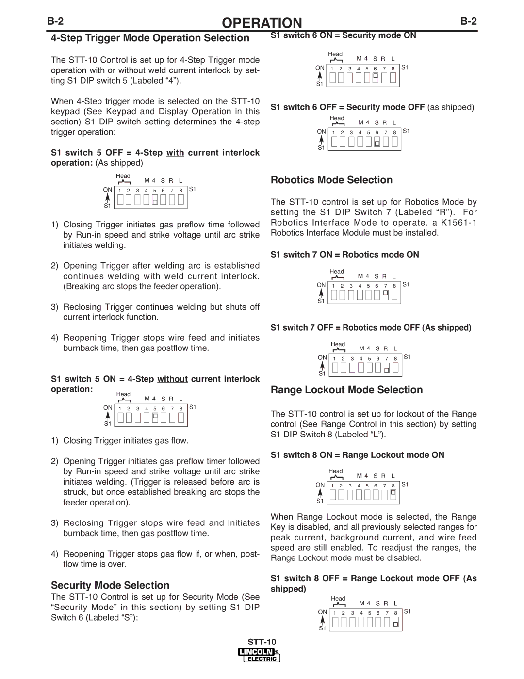
S1 switch 6 ON = Security mode ON
|
| Head |
| M 4 | S R | L |
| ||||||||
ON |
|
|
|
|
|
|
| S1 | |||||||
| 1 | 2 |
| 3 | 4 | 5 | 6 | 7 | 8 |
| |||||
|
|
|
|
|
|
|
|
|
|
|
|
|
|
|
|
|
|
|
|
|
|
|
|
|
|
|
|
|
|
| |
|
|
|
|
|
|
|
|
|
|
|
|
|
|
|
|
S1 |
|
|
|
|
|
|
|
|
|
|
|
|
|
| |
S1 switch 6 OFF = Security mode OFF (as shipped)
|
| Head |
| M 4 | S R | L |
| ||||||||
ON |
|
|
|
|
|
|
| S1 | |||||||
|
|
|
|
|
|
|
|
|
|
|
|
| |||
| 1 | 2 |
| 3 | 4 | 5 | 6 | 7 | 8 |
| |||||
|
|
|
|
|
|
|
|
|
|
|
|
|
|
| |
|
|
|
|
|
|
|
|
|
|
|
|
|
|
|
|
S1 |
|
|
|
|
|
|
|
|
|
|
|
|
|
| |
Robotics Mode Selection
The
S1 switch 7 ON = Robotics mode ON
|
| Head |
| M 4 | S R | L |
| ||||||||
ON |
|
|
|
|
|
|
| S1 | |||||||
| 1 | 2 |
| 3 | 4 | 5 | 6 | 7 | 8 |
| |||||
|
|
|
|
|
|
|
|
|
|
|
|
|
|
|
|
|
|
|
|
|
|
|
|
|
|
|
|
|
|
| |
|
|
|
|
|
|
|
|
|
|
|
|
|
|
|
|
S1 |
|
|
|
|
|
|
|
|
|
|
|
|
|
| |
S1 switch 7 OFF = Robotics mode OFF (As shipped)
| Head |
| M 4 | S R | L |
| ||||||||
ON |
|
|
|
|
|
|
| S1 | ||||||
|
|
|
|
|
|
|
|
|
|
|
|
| ||
1 | 2 |
| 3 | 4 | 5 | 6 | 7 | 8 |
| |||||
S1
Range Lockout Mode Selection
The
S1 switch 8 ON = Range Lockout mode ON
| Head |
| M 4 | S R | L |
| |||||||||
ON |
|
|
|
|
|
|
| S1 | |||||||
|
|
|
|
|
|
|
|
|
|
|
|
|
| ||
1 | 2 |
| 3 | 4 | 5 | 6 | 7 | 8 |
|
| |||||
|
|
|
|
|
|
|
|
|
|
|
|
|
|
|
|
|
|
|
|
|
|
|
|
|
|
|
|
|
|
|
|
S1
When Range Lockout mode is selected, the Range Key is disabled, and all previously selected ranges for peak current, background current, and wire feed speed are still enabled. To readjust the ranges, the Range Lockout mode must be disabled.
S1 switch 8 OFF = Range Lockout mode OFF (As shipped)
|
| Head |
| M 4 | S R | L |
| ||||||||
ON |
|
|
|
|
|
|
| S1 | |||||||
| 1 | 2 |
| 3 | 4 | 5 | 6 | 7 | 8 |
| |||||
|
|
|
|
|
|
|
|
|
|
|
|
|
|
| |
|
|
|
|
|
|
|
|
|
|
|
|
|
|
|
|
S1 |
|
|
|
|
|
|
|
|
|
|
|
|
|
| |