![](/images/new-backgrounds/1190194/190194163x1.webp)
![](/images/new-backgrounds/1190194/190194163xi2.webp)
![](/images/new-backgrounds/1190194/190194163xi3.webp)
Hardware Installation of ATCA-7150 ![](/images/new-backgrounds/1190194/190194163xi5.webp)
![](/images/new-backgrounds/1190194/190194163xi6.webp)
![](/images/new-backgrounds/1190194/190194163xi7.webp)
![](/images/new-backgrounds/1190194/190194163xi8.webp)
![](/images/new-backgrounds/1190194/190194163xi9.webp)
![](/images/new-backgrounds/1190194/190194163xi10.webp)
![](/images/new-backgrounds/1190194/190194163xi11.webp)
![](/images/new-backgrounds/1190194/190194163xi12.webp)
![](/images/new-backgrounds/1190194/190194163xi13.webp)
![](/images/new-backgrounds/1190194/190194163xi14.webp)
![](/images/new-backgrounds/1190194/190194163xi15.webp)
![](/images/new-backgrounds/1190194/190194163xi16.webp)
![](/images/new-backgrounds/1190194/190194163xi17.webp)
![](/images/new-backgrounds/1190194/190194163xi18.webp)
![](/images/new-backgrounds/1190194/190194163xi19.webp)
![](/images/new-backgrounds/1190194/190194163xi20.webp)
![](/images/new-backgrounds/1190194/190194163xi21.webp)
![](/images/new-backgrounds/1190194/190194163xi22.webp)
![](/images/new-backgrounds/1190194/190194163xi23.webp)
![](/images/new-backgrounds/1190194/190194163xi24.webp)
![](/images/new-backgrounds/1190194/190194163xi25.webp)
![](/images/new-backgrounds/1190194/190194163xi26.webp)
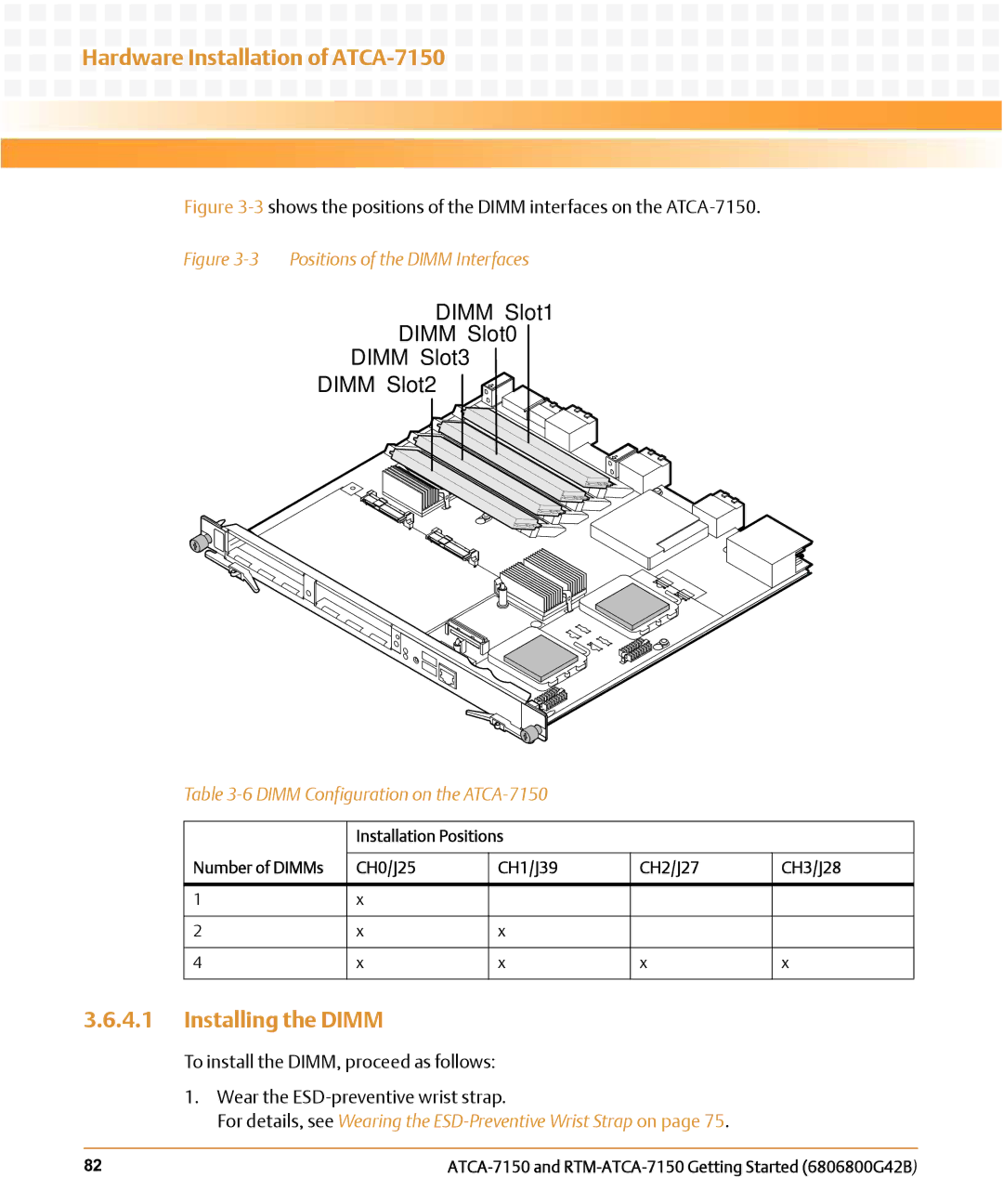
Figure 3-3 shows the positions of the DIMM interfaces on the ATCA-7150.
Figure 3-3 Positions of the DIMM Interfaces
DIMM Slot1
DIMM Slot0
DIMM Slot3
DIMM Slot2
Table 3-6 DIMM Configuration on the ATCA-7150
| Installation Positions |
|
| |
|
|
|
|
|
Number of DIMMs | CH0/J25 | CH1/J39 | CH2/J27 | CH3/J28 |
|
|
|
|
|
1 | x |
|
|
|
|
|
|
|
|
2 | x | x |
|
|
|
|
|
|
|
4 | x | x | x | x |
|
|
|
|
|
3.6.4.1Installing the DIMM
To install the DIMM, proceed as follows:
1.Wear the
For details, see Wearing the ESD-Preventive Wrist Strap on page 75.
82 |