Hardware Installation of
 ATCA-7150 


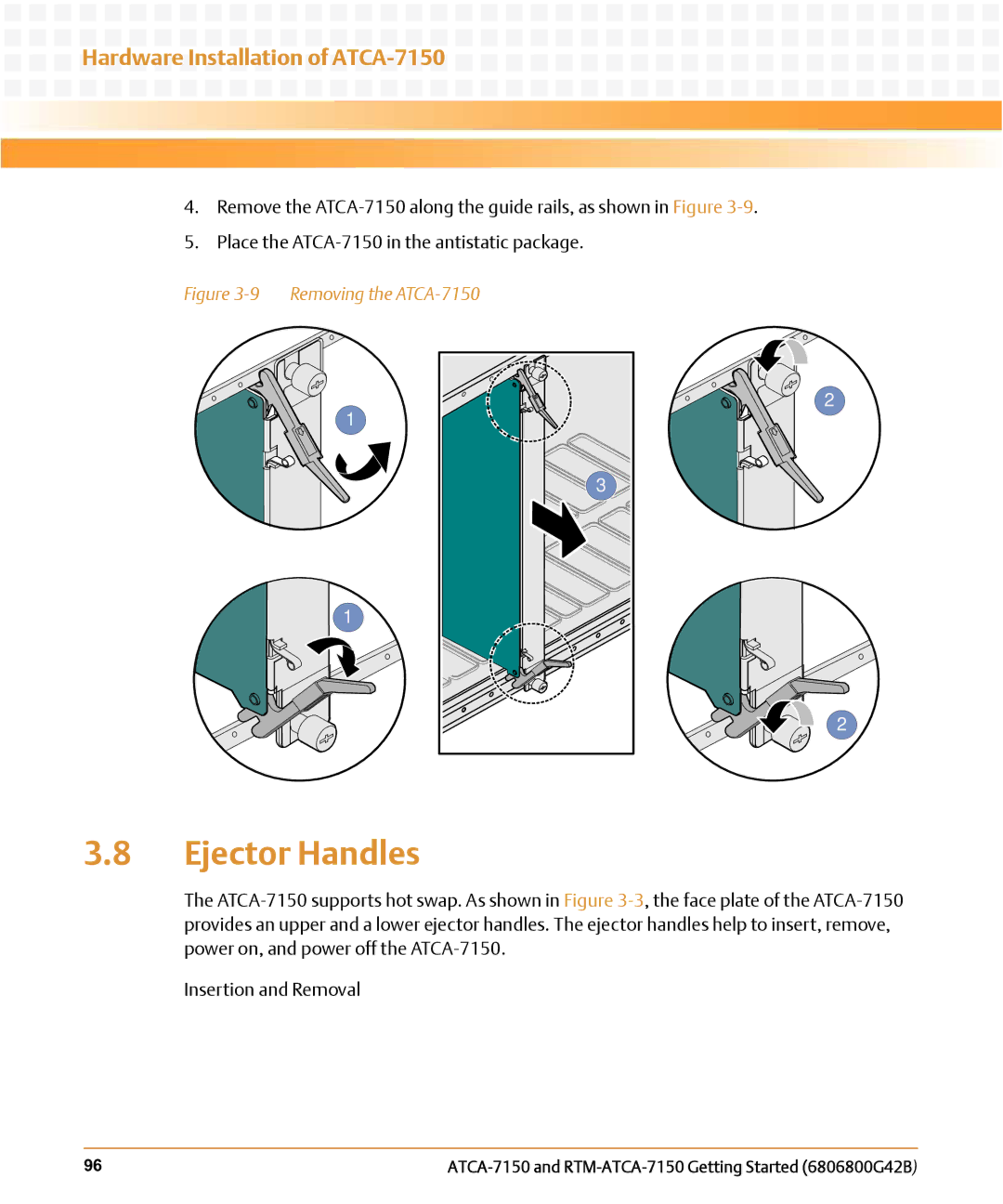
4.Remove the
5.Place the
Figure 3-9 Removing the ATCA-7150
1
3 ![]()
![]()
1
2
2
3.8Ejector Handles
The
Insertion and Removal
96 |
4.Remove the
5.Place the
1
3 ![]()
![]()
1
2
2
The
Insertion and Removal
96 |