OPERATION |
CONTROLS AND SETTINGS
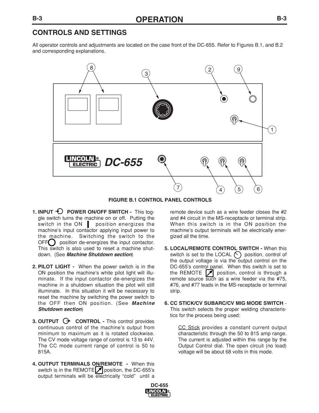
All operator controls and adjustments are located on the case front of the
8 | 2 | 9 |
| 3 |
|
|
|
|
|
|
|
|
|
|
|
|
|
|
|
|
|
|
|
| 1 |
|
|
|
|
|
|
|
|
|
|
|
|
|
|
|
|
|
|
| |
|
|
|
|
|
|
|
|
|
|
|
|
|
|
|
|
|
|
| |
|
|
|
|
|
|
|
|
|
|
|
|
|
|
|
|
|
|
| |
|
|
|
|
|
|
|
|
|
|
|
|
|
|
|
|
|
|
| |
|
|
|
|
|
|
|
|
|
|
|
|
|
|
|
|
|
|
|
|
|
|
|
|
|
|
|
|
|
|
|
|
|
|
|
|
|
|
|
|
|
|
|
|
|
|
|
|
|
|
|
|
|
|
|
|
|
| ||
|
|
|
|
|
|
|
|
|
|
|
|
|
|
|
|
| |||
|
|
|
|
|
|
|
|
|
|
|
|
|
|
|
|
| |||
|
|
|
|
|
|
|
|
|
|
|
|
|
|
|
|
| |||
|
|
|
|
|
|
|
|
|
|
|
|
|
|
|
|
|
|
|
|
|
|
|
|
|
|
|
|
|
|
|
|
|
| 7 |
| 4 | 5 | 6 |
|
|
|
|
|
|
|
|
|
|
|
|
|
|
|
|
|
| |||
|
|
|
|
|
|
|
|
|
|
| FIGURE B.1 CONTROL PANEL CONTROLS |
|
|
|
| ||||
1. INPUT |
| POWER ON/OFF SWITCH - This tog- | remote device such as a wire feeder closes the #2 | ||||||||||||||||
gle switch turns the machine on or off. Putting the | and #4 circuit in the | ||||||||||||||||||
switch in the ON |
|
| position energizes the | When this switch is in the ON position the | |||||||||||||||
machine’s input contactor applying input power to | machine’s output terminals will be electrically ener- | ||||||||||||||||||
the machine . Switching the switch to the | gized all the time. |
|
|
|
| ||||||||||||||
OFF | position |
|
|
|
|
|
| ||||||||||||
This switch is also used to reset a machine shut- | 5. LOCAL/REMOTE CONTROL SWITCH - When this | ||||||||||||||||||
down. (See Machine Shutdown section) | switch is set to the LOCAL | position, control of | |||||||||||||||||
|
|
|
|
|
|
|
|
|
|
|
|
|
| the output voltage is via the output control on the | |||||
2. PILOT LIGHT - When the power switch is in the | When this switch is set to | ||||||||||||||||||
ON position the machine’s white pilot light will illu- | the REMOTE |
| position, control is through a | ||||||||||||||||
minate. | If the input contactor | remote source | such as a wire feeder via the #75, | ||||||||||||||||
machine in a shutdown situation the pilot will still | #76, and #77 leads in the | ||||||||||||||||||
illuminate. In this situation it will be necessary to | strip. |
|
|
|
| ||||||||||||||
reset the machine by switching the power switch to |
|
|
|
|
|
| |||||||||||||
the OFF then ON position . (See Machine | 6. CC STICK/CV SUBARC/CV MIG MODE SWITCH - | ||||||||||||||||||
Shutdown section) |
|
|
|
|
|
| This switch selects the proper welding characteris- | ||||||||||||
|
|
|
|
|
|
|
|
|
|
|
|
|
| tics for the process being used: |
|
| |||
3.OUTPUT ![]() CONTROL - This control provides
CONTROL - This control provides
continuous control of the machine’s output from | CC Stick provides a constant current output | ||
minimum to maximum as it is rotated clockwise. | characteristic through the 50 to 815 amp range. | ||
The CV mode voltage range of control is 13 to 44V. | The current is adjusted within this range by the | ||
The CC mode current range of control is 50 to | Output Control dial. The open circuit (no load) | ||
815A. | voltage will be about 68 volts in this mode. | ||
4. OUTPUT TERMINALS ON/REMOTE - When this |
| ||
switch is in the REMOTE |
| position, the |
|
output terminals will be | electrically “cold” until a |
| |
|
|
| |