Manuals
/
Lincoln Electric
/
Power Tools
/
Soldering Gun
Lincoln Electric
IM718
manual
Dimension Print
Models:
IM718
1
1
2
3
4
5
6
7
8
9
10
11
12
13
14
15
16
17
18
19
20
21
22
23
24
25
26
27
28
29
30
31
32
33
34
35
36
37
38
39
40
41
42
43
44
45
46
47
48
48
Download
48 pages
8.92 Kb
37
38
39
40
41
42
43
44
45
46
Troubleshooting
Specification
Install
Error codes
Connection Diagram
Dimension
Maintenance
Accessories
PIN, Lead Connector Setups
External I/O Connector
Page 42
Image 42
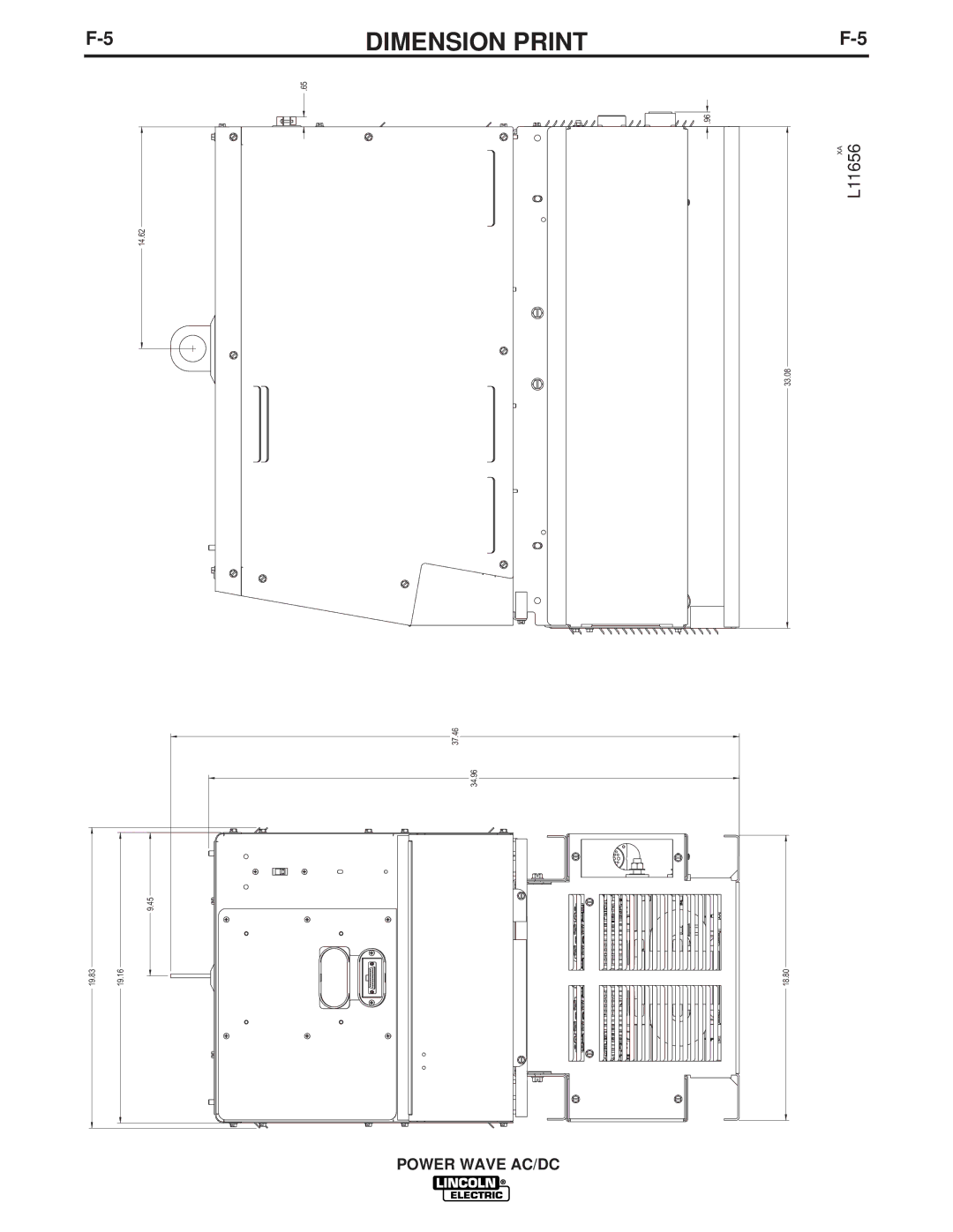
F-5
14.62
9.45
19.83
19.16
DIMENSION PRINT
F-5
.65
.96
XA
L11656
33.08
37.46
34.96
18.80
POWER WAVE AC/DC
Page 41
Page 43
Page 42
Image 42
Page 41
Page 43
Contents
Power Wave AC/DC
Safety
Power Wave AC/DC
Electric Shock can kill
Welding Sparks can cause fire or explosion
Iii
Précautions DE Sûreté
Sûreté Pour Soudage a L’Arc
Thank You
Table of Contents
Installation
Technical Specifications Power Wave AC/DC K1860-1
Lifting
Machine Grounding
High Frequency Protection
Stacking
Input Fuse and Supply Wire Considerations
Input Connection
Welding with Multiple UNSYN- Chronized Power Waves
TWO Power Waves
Best
Electrode and Work Cable Connections
Cable INDUCTANCE, and ITS Effects on Pulse Welding
Voltage Sensing
Table A.2
Electrode Voltage Sensing
Control Cable Specifications
Ethernet Connections
External I/O Connector
High Speed Gear BOX
Control Board DIP Switch
Feed Head Board DIP Switch
Ethernet Board DIP Switch
Table A.4 Object Instance
Devicenet MAC ID Table A.5
Bank S3 and S4
ARC
MULTI-ARC System Description
Safety Precuations
Operation
Power Wave AC/DC
Definition of Welding Terms
General Description
Recommended Processes and Equipment
Required Equipment
Case Front Controls
Welder Operation
Making a Weld
Welding Mode
Welding Adjustments
General Welding Adjustments
Volts / Trim
7OPERATIONB-7
CV Welding
Pulse Welding
Figure B.3
Field Installed Options / Accessories
Accessories
Factory Installed
Optional Equipment
Maintenance
Periodic Maintenance
Calibration Specification
Troubleshooting
HOW to USE Troubleshooting Guide
Authorized Field Service Facility
Contact your local Lincoln
Rear of the machine
Contact your local Lincoln Authorized Field Service Facility
Possible Areas Recommended Symptoms
Field Service Facility
Your local Lincoln Authorized
Using the Status LED to Troubleshoot System Problems
Before the machine is turned off
Error Codes for the Powerwave
Error Code # Indication
Left Side of Machine
G4076-2
Rectifier
Table F.4 RS232 Connector S3
PIN, Lead Connector Setups
Table F.5 Devicenet Connector S5
Table F.6 External I/O S7
Connection Diagram
Robotic Set Up, Electrode Positive, CV/Pulse Configuration
Dimension Print
Power Wave AC/DC
Power Wave AC/DC
Basic Course
$700.00
Precaucion
Warnung
Top
Page
Image
Contents