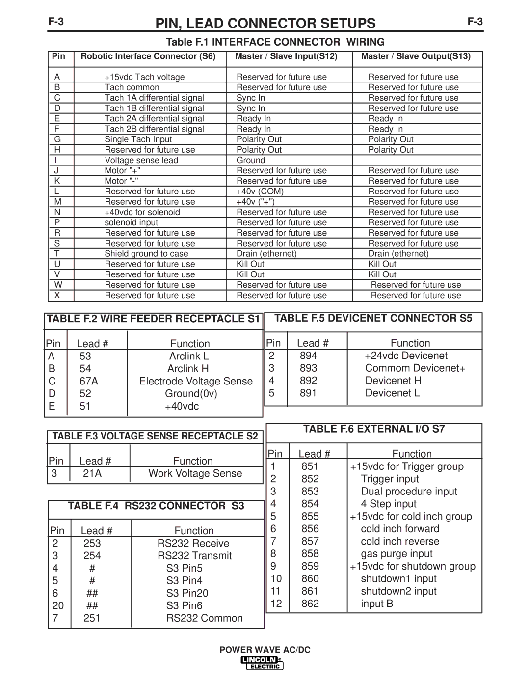
PIN, LEAD CONNECTOR SETUPS | |||||||||
|
|
|
|
|
|
|
|
|
|
|
|
|
|
|
|
|
|
|
|
|
|
| Table F.1 INTERFACE CONNECTOR WIRING |
|
|
| |||
|
|
|
|
|
|
|
| ||
| Pin | Robotic Interface Connector (S6) | Master / Slave Input(S12) | Master / Slave Output(S13) |
| ||||
|
|
|
|
|
|
|
| ||
| A | +15vdc Tach voltage | Reserved for future use | Reserved for future use |
|
|
| ||
| B | Tach common | Reserved for future use | Reserved for future use |
|
|
| ||
| C | Tach 1A differential signal | Sync In | Reserved for future use |
|
|
| ||
| D | Tach 1B differential signal | Sync In | Reserved for future use |
|
|
| ||
| E | Tach 2A differential signal | Ready In | Ready In |
|
|
| ||
| F | Tach 2B differential signal | Ready In | Ready In |
|
|
| ||
| G | Single Tach Input | Polarity Out | Polarity Out |
|
|
| ||
| H | Reserved for future use | Polarity Out | Polarity Out |
|
|
| ||
| I | Voltage sense lead | Ground |
|
|
|
|
| |
| J | Motor "+" | Reserved for future use | Reserved for future use |
|
|
| ||
| K | Motor | Reserved for future use | Reserved for future use |
|
|
| ||
| L | Reserved for future use | +40v (COM) | Reserved for future use |
|
|
| ||
| M | Reserved for future use | +40v ("+") | Reserved for future use |
|
|
| ||
| N | +40vdc for solenoid | Reserved for future use | Reserved for future use |
|
|
| ||
| P | solenoid input | Reserved for future use | Reserved for future use |
|
|
| ||
| R | Reserved for future use | Reserved for future use | Reserved for future use |
|
|
| ||
| S | Reserved for future use | Reserved for future use | Reserved for future use |
|
|
| ||
| T | Shield ground to case | Drain (ethernet) | Drain (ethernet) |
|
|
| ||
| U | Reserved for future use | Kill Out | Kill Out |
|
|
| ||
| V | Reserved for future use | Kill Out | Kill Out |
|
|
| ||
| W | Reserved for future use | Reserved for future use | Reserved for future use |
|
|
| ||
| X | Reserved for future use | Reserved for future use | Reserved for future use |
|
|
| ||
TABLE F.2 WIRE FEEDER RECEPTACLE S1
Pin | Lead # |
| Function |
| |||
A | 53 |
| Arclink L |
B | 54 |
| Arclink H |
C | 67A |
| Electrode Voltage Sense |
D | 52 |
| Ground(0v) |
E | 51 |
| +40vdc |
|
|
|
|
|
|
|
|
TABLE F.5 DEVICENET CONNECTOR S5
Pin | Lead # | Function |
2 | 894 | +24vdc Devicenet |
3 | 893 | Commom Devicenet+ |
4 | 892 | Devicenet H |
5 | 891 | Devicenet L |
|
|
|
TABLE F.3 VOLTAGE SENSE RECEPTACLE S2
| Pin |
| Lead # |
| Function |
| |
|
|
| |||||
| 3 |
| 21A |
| Work Voltage Sense | ||
|
|
|
|
|
|
|
|
|
|
|
|
|
|
|
|
|
| TABLE F.4 RS232 CONNECTOR S3 | |||||
|
|
|
|
|
|
| |
| Pin |
| Lead # | Function | |||
| 2 |
| 253 |
| RS232 Receive | ||
| 3 |
| 254 |
| RS232 Transmit | ||
| 4 |
| # |
| S3 | Pin5 | |
| 5 |
| # |
| S3 | Pin4 | |
| 6 |
| ## |
| S3 | Pin20 | |
| 20 |
| ## |
| S3 | Pin6 | |
| 7 |
| 251 |
| RS232 Common | ||
|
|
|
|
|
|
|
|
TABLE F.6 EXTERNAL I/O S7
Pin | Lead # | Function |
1 | 851 | +15vdc for Trigger group |
2 | 852 | Trigger input |
3 | 853 | Dual procedure input |
4 | 854 | 4 Step input |
5 | 855 | +15vdc for cold inch group |
6 | 856 | cold inch forward |
7 | 857 | cold inch reverse |
8 | 858 | gas purge input |
9 | 859 | +15vdc for shutdown group |
10 | 860 | shutdown1 input |
11 | 861 | shutdown2 input |
12 | 862 | input B |
|
|
|
