INSTALLATION | ||
|
|
|
WELDING WITH MULTIPLE UNSYN- CHRONIZED POWER WAVES
CAUTION
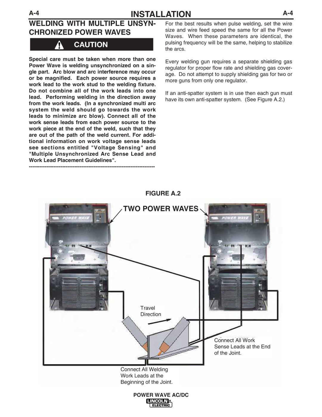
Special care must be taken when more than one Power Wave is welding unsynchronized on a sin- gle part. Arc blow and arc interference may occur or be magnified. Each power source requires a work lead to the work stud to the welding fixture. Do not combine all of the work leads into one lead. Performing welding in the direction away from the work leads. (In a synchronized multi arc system the weld should go towards the work leads to minimize arc blow). Connect all of the work sense leads from each power source to the work piece at the end of the weld, such that they are out of the path of the weld current. For addi- tional information on work voltage sense leads see sections entitled "Voltage Sensing" and "Multiple Unsynchronized Arc Sense Lead and Work Lead Placement Guidelines".
For the best results when pulse welding, set the wire size and wire feed speed the same for all the Power Waves. When these parameters are identical, the pulsing frequency will be the same, helping to stabilize the arcs.
Every welding gun requires a separate shielding gas regulator for proper flow rate and shielding gas cover- age. Do not attempt to supply shielding gas for two or more guns from only one regulator.
If an
FIGURE A.2
TWO POWER WAVES
Travel
Direction
Connect All Work
Sense Leads at the End
of the Joint.
Connect All Welding
Work Leads at the
Beginning of the Joint.