B-10 OPERATION
GUN SWITCHES
Gun Trigger Switch — Turns on arc voltage, wire feeder, and gas solenoid (except with Innershield) when closed. Also causes the screen to display the Auto or Manual screens (depending on which mode it is in), when the trigger is pulled. Turns off arc voltage, wire feeder, and gas solenoid when opened.
NOTE: If using Slow
Gun Thumbswitch (Magnum™ 250SP Only) — Used to control wire feed speed, arc voltage, or selec- tion of toggle memories 4 and 5. See IPM VOLTS key and Toggle key for control details. The increase or decrease function of the thumbswitch is the same as the center and right arrow key pairs for IPM or VOLTS setting. (See Arrow keys in “Setup Keys” section for details.)
WIRE DRIVE ROLL
The drive roll provided with the
PROCEDURE FOR CHANGING DRIVE ROLL
Different wire sizes may require changing the drive roll. The applicable wire sizes are stamped on the drive roll. Dual groove rolls must be installed so the side with the proper wire size stamp faces out.
1 Turn off the power source.
2.Release the pressure on the idle roll by swinging the pressure arm off the idle roll arm.
3.Remove the wire from the drive system.
IDEALARC
4.Remove the thumbscrew from the drive roll. Turn the drive roll over or change to another roll as required. Reinstall the thumbscrew.
5.Be sure the gun liner and contact tip are properly sized for wire being used. (See Gun and Cable Maintenance section.)
WIRE REEL LOADING
MOUNTING OF 22 TO 30 LB. READI-
REELS
To mount a
1.Remove the locking collar from the 2" O.D. spindle and mount the K363P Adapter so the spindle pin engages the hole provided in the Adapter. Replace and tighten the locking collar.
2.Rotate the spindle and adapter so the retaining spring is at the 12 o’clock position.
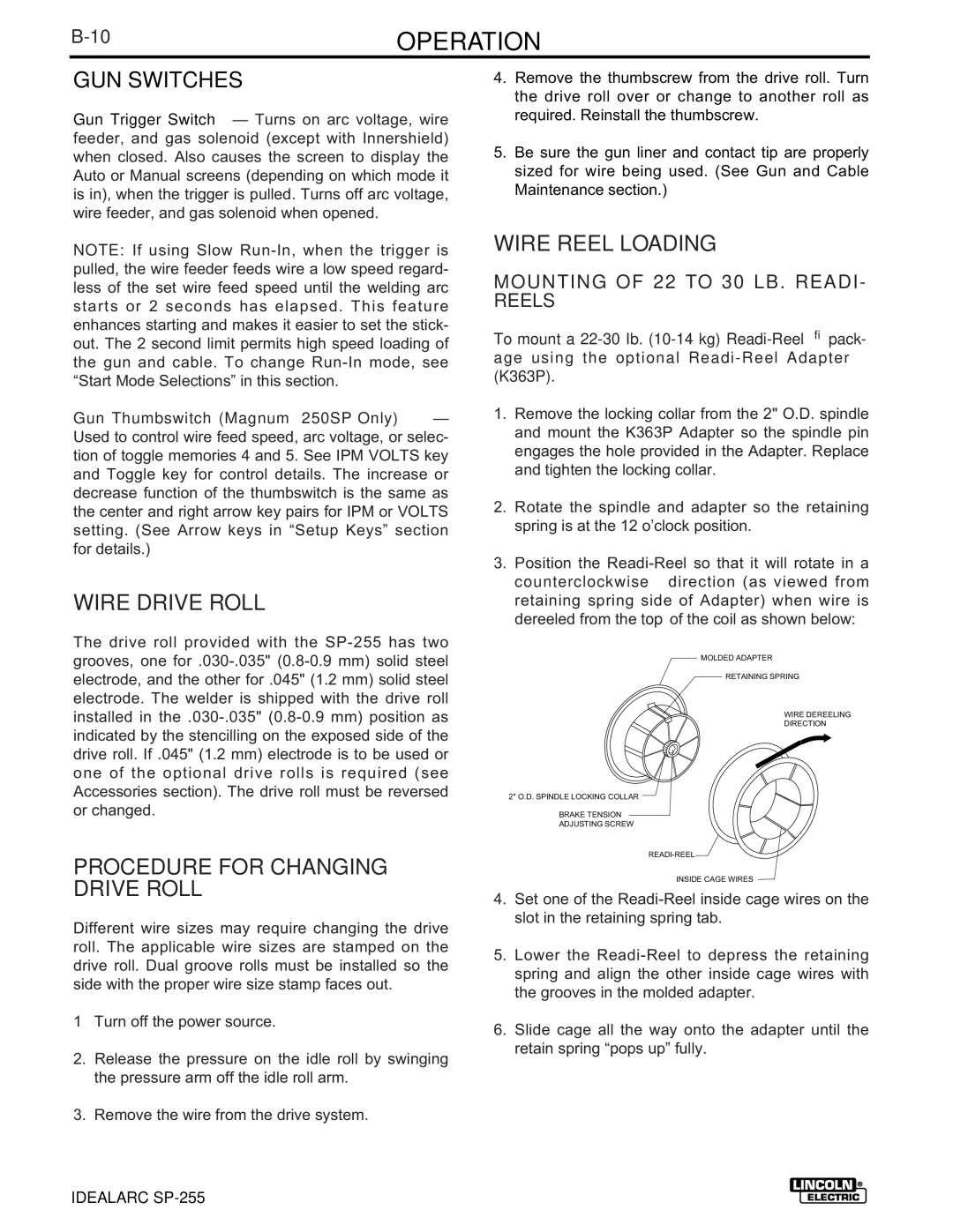
3.Position the
MOLDED ADAPTER
RETAINING SPRING
WIRE DEREELING
DIRECTION
2" O.D. SPINDLE LOCKING COLLAR
BRAKE TENSION
ADJUSTING SCREW
INSIDE CAGE WIRES
4.Set one of the
5.Lower the
6.Slide cage all the way onto the adapter until the retain spring “pops up” fully.