INSTALLATIONA-3
The 230/460/575 volt 60 Hz model is not equipped with a plug, input cable or receptacle.
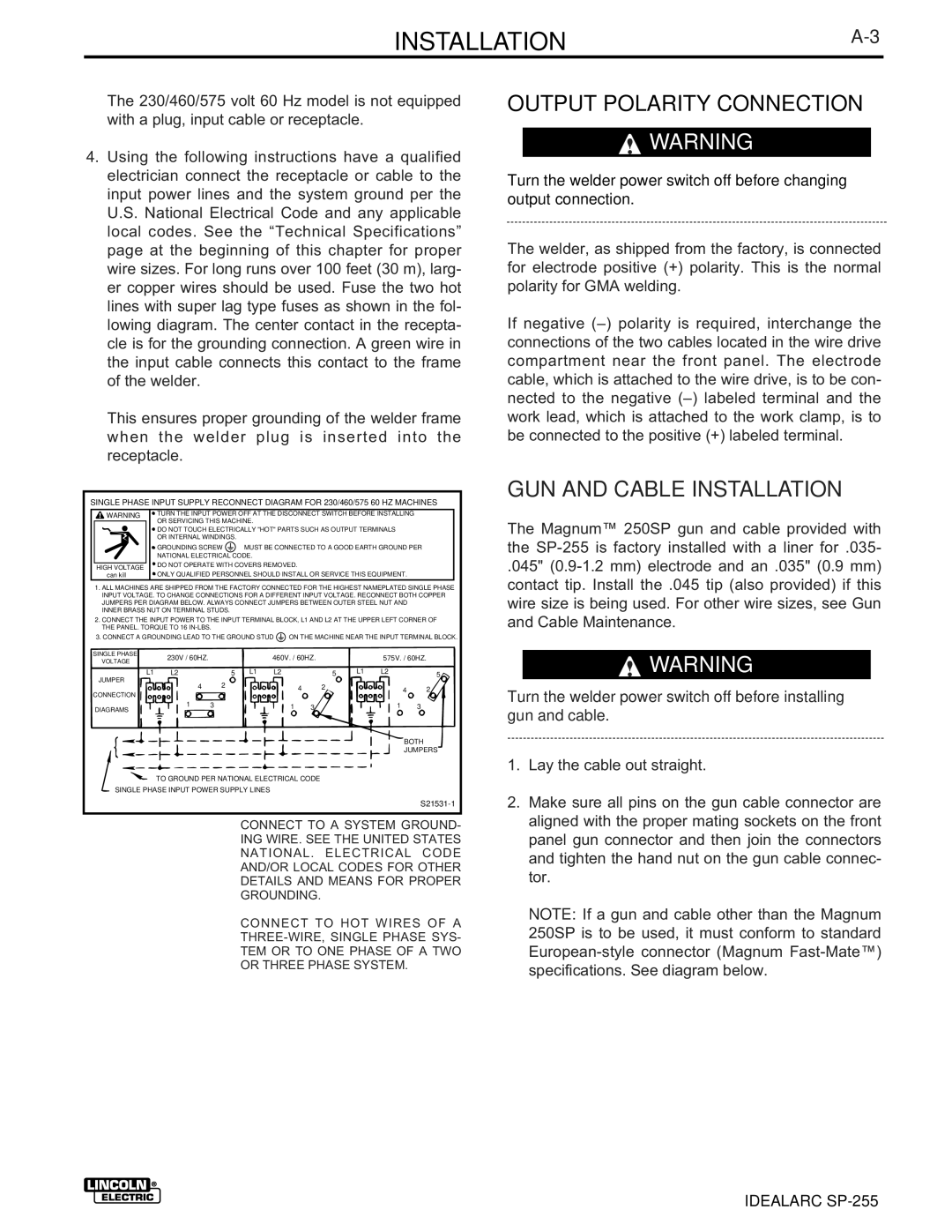
4.Using the following instructions have a qualified electrician connect the receptacle or cable to the input power lines and the system ground per the U.S. National Electrical Code and any applicable local codes. See the “Technical Specifications” page at the beginning of this chapter for proper wire sizes. For long runs over 100 feet (30 m), larg- er copper wires should be used. Fuse the two hot lines with super lag type fuses as shown in the fol- lowing diagram. The center contact in the recepta- cle is for the grounding connection. A green wire in the input cable connects this contact to the frame of the welder.
This ensures proper grounding of the welder frame when the welder plug is inserted into the receptacle.
SINGLE PHASE INPUT SUPPLY RECONNECT DIAGRAM FOR 230/460/575 60 HZ MACHINES
| WARNING |
| TURN THE INPUT POWER OFF AT THE DISCONNECT SWITCH BEFORE INSTALLING | |||
|
|
| OR SERVICING THIS MACHINE. | |||
|
|
| DO NOT TOUCH ELECTRICALLY "HOT" PARTS SUCH AS OUTPUT TERMINALS | |||
|
|
| OR INTERNAL WINDINGS. |
| ||
|
|
| GROUNDING SCREW |
|
| MUST BE CONNECTED TO A GOOD EARTH GROUND PER |
|
|
|
|
| ||
|
|
| ||||
|
|
| NATIONAL ELECTRICAL CODE. | |||
|
|
| DO NOT OPERATE WITH COVERS REMOVED. | |||
| HIGH VOLTAGE | |||||
|
| ONLY QUALIFIED PERSONNEL SHOULD INSTALL OR SERVICE THIS EQUIPMENT. | ||||
| can kill |
| ||||
1.ALL MACHINES ARE SHIPPED FROM THE FACTORY CONNECTED FOR THE HIGHEST NAMEPLATED SINGLE PHASE INPUT VOLTAGE. TO CHANGE CONNECTIONS FOR A DIFFERENT INPUT VOLTAGE. RECONNECT BOTH COPPER JUMPERS PER DIAGRAM BELOW. ALWAYS CONNECT JUMPERS BETWEEN OUTER STEEL NUT AND
INNER BRASS NUT ON TERMINAL STUDS.
2.CONNECT THE INPUT POWER TO THE INPUT TERMINAL BLOCK, L1 AND L2 AT THE UPPER LEFT CORNER OF THE PANEL. TORQUE TO 16
3.CONNECT A GROUNDING LEAD TO THE GROUND STUD ![]() ON THE MACHINE NEAR THE INPUT TERMINAL BLOCK.
ON THE MACHINE NEAR THE INPUT TERMINAL BLOCK.
SINGLE PHASE | 230V / 60HZ. |
|
|
| 460V. / 60HZ. |
|
| 575V. / 60HZ. | ||
VOLTAGE |
|
|
|
|
| |||||
|
|
|
|
|
|
|
|
|
| |
L1 | L2 |
| 5 | L1 | L2 |
| 5 | L1 | L2 | 5 |
JUMPER | 4 | 2 |
|
|
| 2 |
|
|
|
|
CONNECTION |
|
| 4 |
|
| 4 | 2 | |||
|
|
|
|
|
|
|
|
|
| |
DIAGRAMS | 1 | 3 |
|
| 1 | 3 |
|
| 1 | 3 |
BOTH
JUMPERS
TO GROUND PER NATIONAL ELECTRICAL CODE
SINGLE PHASE INPUT POWER SUPPLY LINES
CONNECT TO A SYSTEM GROUND-
ING WIRE. SEE THE UNITED STATES
NATIONAL. ELECTRICAL CODE
AND/OR LOCAL CODES FOR OTHER
DETAILS AND MEANS FOR PROPER
GROUNDING.
CONNECT TO HOT WIRES OF A
TEM OR TO ONE PHASE OF A TWO
OR THREE PHASE SYSTEM.
OUTPUT POLARITY CONNECTION
![]() WARNING
WARNING
Turn the welder power switch off before changing output connection.
The welder, as shipped from the factory, is connected for electrode positive (+) polarity. This is the normal polarity for GMA welding.
If negative
GUN AND CABLE INSTALLATION
The Magnum™ 250SP gun and cable provided with the
.045"
![]() WARNING
WARNING
Turn the welder power switch off before installing gun and cable.
1.Lay the cable out straight.
2.Make sure all pins on the gun cable connector are aligned with the proper mating sockets on the front panel gun connector and then join the connectors and tighten the hand nut on the gun cable connec- tor.
NOTE: If a gun and cable other than the Magnum 250SP is to be used, it must conform to standard
IDEALARC