Return to Section TOC
Return to Section TOC
Return to Master TOC
Return to Master TOC
| INSTALLATION | |||||||||||
|
|
|
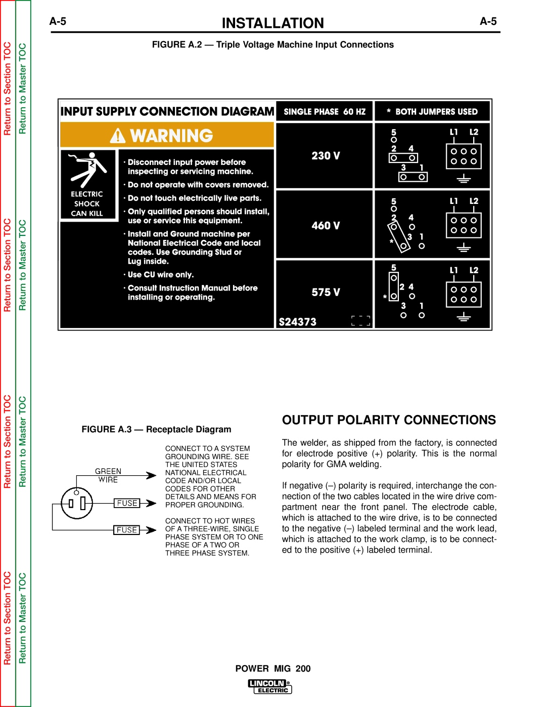
| FIGURE A.2 — Triple Voltage Machine Input Connections |
|
|
| |||||
|
|
|
|
|
|
|
|
|
|
|
|
|
|
|
|
|
|
|
|
|
|
|
|
|
|
|
|
|
|
|
|
|
|
|
|
|
|
|
|
|
|
|
|
|
|
|
|
|
|
|
|
|
|
|
|
|
|
|
|
|
|
|
|
|
|
|
|
|
|
|
|
|
|
|
|
|
|
|
|
|
|
|
|
|
|
|
|
|
|
|
Return to Section TOC
Return to Master TOC
FIGURE A.3 — Receptacle Diagram
CONNECT TO A SYSTEM
GROUNDING WIRE. SEE
THE UNITED STATES
NATIONAL ELECTRICAL
CODE AND/OR LOCAL
CODES FOR OTHER
DETAILS AND MEANS FOR
PROPER GROUNDING.
CONNECT TO HOT WIRES
OF A
PHASE SYSTEM OR TO ONE
PHASE OF A TWO OR
THREE PHASE SYSTEM.
OUTPUT POLARITY CONNECTIONS
The welder, as shipped from the factory, is connected for electrode positive (+) polarity. This is the normal polarity for GMA welding.
If negative
Return to Section TOC
Return to Master TOC
POWER MIG 200