THEORY OF OPERATION |
Return to Section TOC
Return to Section TOC
Return to Master TOC
Return to Master TOC
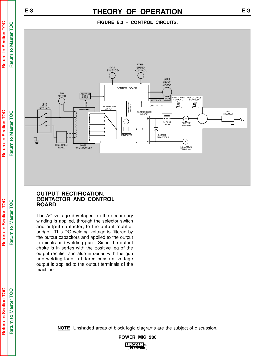
FIGURE E.3 – CONTROL CIRCUITS.
|
|
| WIRE |
|
|
| GAS |
| SPEED |
|
|
| SOLENOID |
| CONTROL |
|
|
|
|
| WIRE |
|
|
|
|
| DRIVE |
|
|
|
|
| MOTOR |
|
|
| CONTROL BOARD |
|
| ||
FAN | RECTIFIER |
|
|
|
|
MOTOR | DIODE |
|
| TRANSFORMER | OUTPUT BRIDGE |
| BRIDGE |
| TACH | ||
| 28VAC | CONTACTOR CONTROL | FEEDBACK | THERMOSTAT | THERMOSTAT |
LINE | GUN TRIGGER |
|
| ||
SWITCH | TAP SELECTOR |
|
|
| |
|
|
|
| ||
SWITCH |
|
|
|
| |
|
|
|
|
| |
|
|
| OUTPUT DIODE |
|
|
|
|
| BRIDGE |
|
|
|
|
| + | + |
|
|
|
| OUTPUT | POSITIVE | |
|
|
| CHOKE | ||
|
|
| TERMINAL | ||
|
|
|
| ||
|
| CONTACTOR | OUTPUT |
|
|
|
|
| CAPACITORS |
|
|
RECONNECT |
|
| - | - |
|
MAIN |
|
| NEGATIVE | ||
PANEL | TRANSFORMER |
|
| ||
|
| TERMINAL | |||
|
|
|
| ||
GUN
ASSEMBLY
Return to Section TOC
Return to Section TOC
Return to Master TOC
Return to Master TOC
OUTPUT RECTIFICATION,
CONTACTOR AND CONTROL
BOARD
The AC voltage developed on the secondary winding is applied, through the selector switch and output contactor, to the output rectifier bridge. This DC welding voltage is filtered by the output capacitors and applied to the output terminals and welding gun. Since the output choke is in series with the positive leg of the output rectifier and also in series with the gun and welding load, a filtered constant voltage output is applied to the output terminals of the machine.
NOTE: Unshaded areas of block logic diagrams are the subject of discussion.