Return to Section TOC
Return to Section TOC
Return to Master TOC
Return to Master TOC
TROUBLESHOOTING AND REPAIR | ||
|
|
|
WIRE DRIVE MOTOR ASSEMBLY REPLACEMENT (Continued)
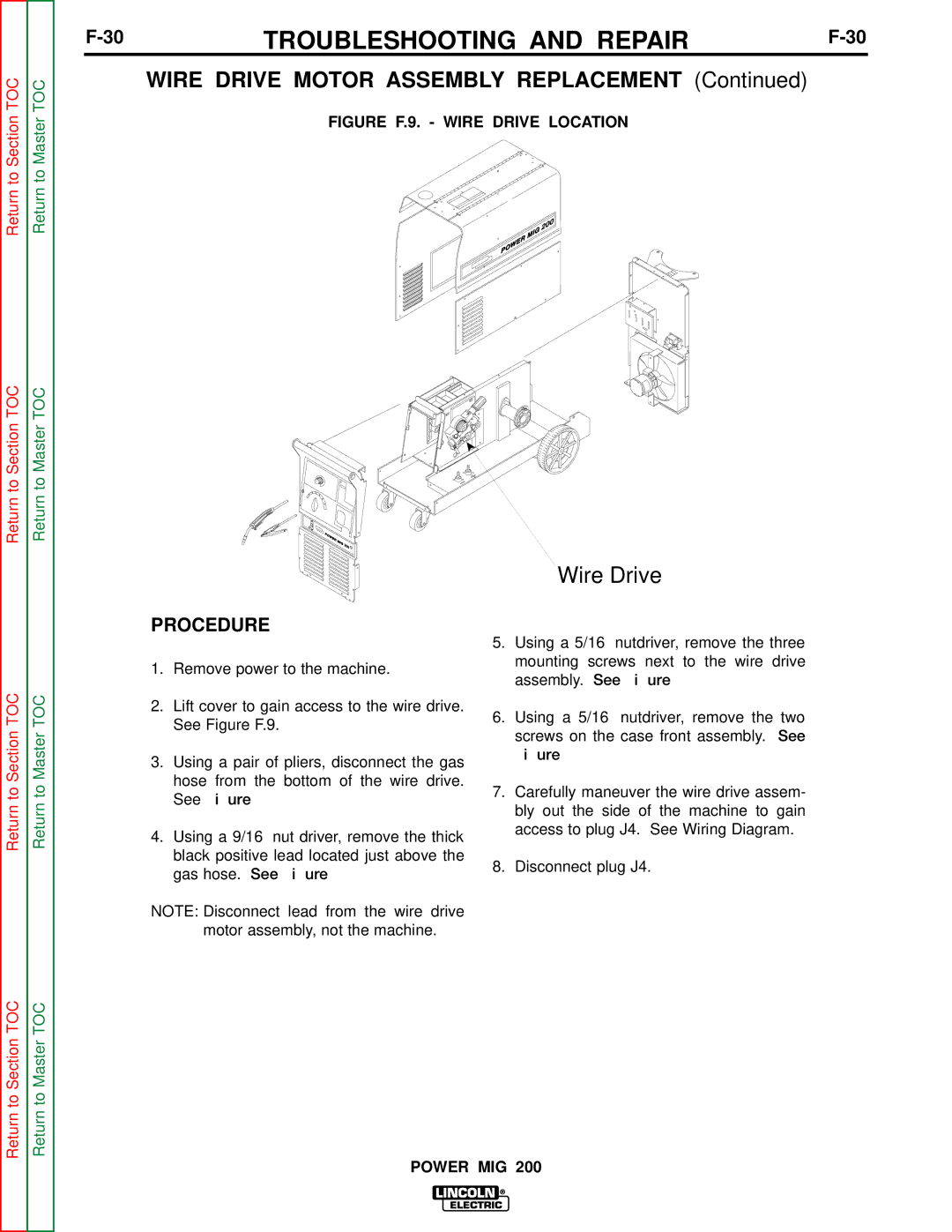
FIGURE F.9. - WIRE DRIVE LOCATION
Wire Drive
Return to Section TOC
Return to Section TOC
Return to Master TOC
Return to Master TOC
PROCEDURE
1.Remove power to the machine.
2.Lift cover to gain access to the wire drive. See Figure F.9.
3.Using a pair of pliers, disconnect the gas hose from the bottom of the wire drive. See Figure F.10.
4.Using a 9/16” nut driver, remove the thick black positive lead located just above the gas hose. See Figure F.10.
NOTE: Disconnect lead from the wire drive motor assembly, not the machine.
5.Using a 5/16” nutdriver, remove the three mounting screws next to the wire drive assembly. See Figure F.10.
6.Using a 5/16” nutdriver, remove the two screws on the case front assembly. See
Figure F.11.
7.Carefully maneuver the wire drive assem- bly out the side of the machine to gain access to plug J4. See Wiring Diagram.
8.Disconnect plug J4.