Return to Section TOC
Return to Master TOC
THEORY OF OPERATION | ||
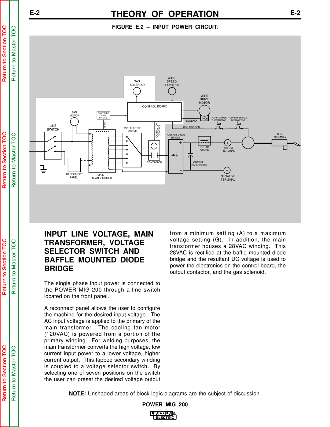
| FIGURE E.2 – INPUT POWER CIRCUIT. |
|
Return to Section TOC
Return to Master TOC
LINE
SWITCH
|
|
| WIRE |
|
|
| GAS |
| SPEED |
|
|
| SOLENOID |
| CONTROL |
|
|
|
|
| WIRE |
|
|
|
|
| DRIVE |
|
|
|
|
| MOTOR |
|
|
| CONTROL BOARD |
|
| ||
FAN | RECTIFIER |
|
|
|
|
MOTOR | DIODE |
|
| TRANSFORMER | OUTPUT BRIDGE |
| BRIDGE |
| TACH | ||
|
|
| THERMOSTAT | THERMOSTAT | |
| 28VAC | CONTACTOR CONTROL | FEEDBACK | ||
| GUN TRIGGER |
|
| ||
| TAP SELECTOR |
|
|
| |
|
|
|
|
| |
| SWITCH |
|
|
|
|
|
|
| OUTPUT DIODE |
|
|
|
|
| BRIDGE |
|
|
|
|
| + | + |
|
|
|
| OUTPUT | POSITIVE | |
|
|
| CHOKE | ||
|
|
| TERMINAL | ||
|
|
|
| ||
|
| CONTACTOR | OUTPUT |
|
|
|
|
| CAPACITORS |
|
|
RECONNECT |
|
| - | - |
|
MAIN |
|
| NEGATIVE | ||
PANEL | TRANSFORMER |
|
| ||
|
| TERMINAL | |||
|
|
|
| ||
GUN
ASSEMBLY
Return to Section TOC
Return to Section TOC
Return to Master TOC
Return to Master TOC
INPUT LINE VOLTAGE, MAIN | from a minimum setting (A) to a maximum | |
TRANSFORMER, VOLTAGE | voltage setting (G). In addition, the main | |
transformer houses a 28VAC winding. This | ||
SELECTOR SWITCH AND | ||
28VAC is rectified at the baffle mounted diode | ||
BAFFLE MOUNTED DIODE | bridge and the resultant DC voltage is used to | |
BRIDGE | power the electronics on the control board, the | |
output contactor, and the gas solenoid. | ||
| ||
The single phase input power is connected to |
| |
the POWER MIG 200 through a line switch |
| |
located on the front panel. |
| |
A reconnect panel allows the user to configure |
| |
the machine for the desired input voltage. The |
| |
AC input voltage is applied to the primary of the |
| |
main transformer. The cooling fan motor |
| |
(120VAC) is powered from a portion of the |
| |
primary winding. For welding purposes, the |
| |
main transformer converts the high voltage, low |
| |
current input power to a lower voltage, higher |
| |
current output. This tapped secondary winding |
| |
is coupled to a voltage selector switch. By |
| |
selecting one of seven positions on the switch |
| |
the user can preset the desired voltage output |
|
NOTE: Unshaded areas of block logic diagrams are the subject of discussion.
