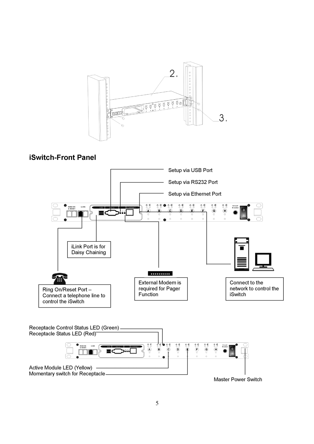
iSwitch-Front Panel
Setup via USB Port
Setup via RS232 Port
Setup via Ethernet Port
iLink Port is for Daisy Chaining
|
|
|
|
|
|
|
|
|
|
|
|
|
|
|
|
|
| External Modem is | ||
Ring On/Reset | Port – |
| required for Pager | |||
Connect a telephone line to |
| Function | ||||
control the iSwitch |
|
|
|
| ||
|
|
| ||||
|
|
|
|
|
|
|
Receptacle Control Status LED (Green)
Receptacle Status LED (Red)
Active Module LED (Yellow)
Momentary switch for Receptacle
Connect to the network to control the iSwitch
Master Power Switch
5