ADSL2 Gateway with 4-Port Switch
IMPORTANT: For countries that have phone jacks with
For countries that do not have phone jacks with
Annex B users (E1 and DE versions of the Gateway) must use the included special cable to connect the gateway to the wall jack
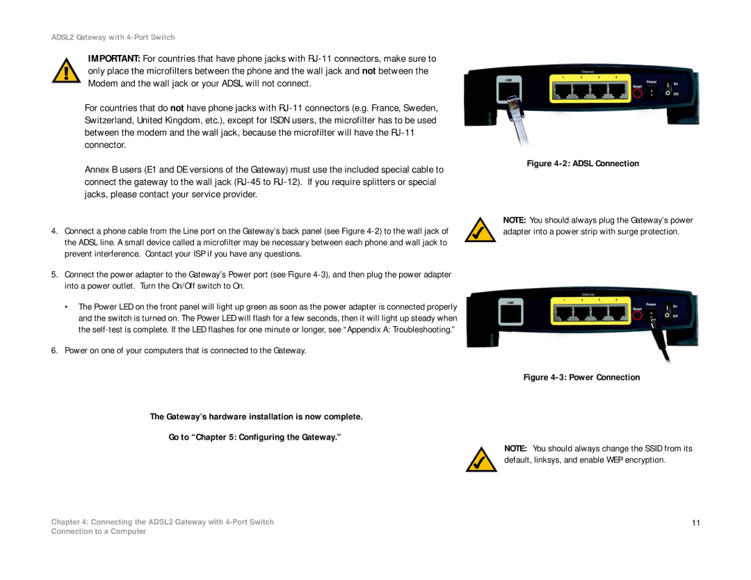
4.Connect a phone cable from the Line port on the Gateway’s back panel (see Figure
5.Connect the power adapter to the Gateway’s Power port (see Figure
•The Power LED on the front panel will light up green as soon as the power adapter is connected properly and the switch is turned on. The Power LED will flash for a few seconds, then it will light up steady when the
6.Power on one of your computers that is connected to the Gateway.
The Gateway’s hardware installation is now complete.
Go to “Chapter 5: Configuring the Gateway.”
Chapter 4: Connecting the ADSL2 Gateway with
Figure 4-2: ADSL Connection
NOTE: You should always plug the Gateway’s power adapter into a power strip with surge protection.
Figure 4-3: Power Connection
NOTE: You should always change the SSID from its default, linksys, and enable WEP encryption.
11
Connection to a Computer