Service Manual
3Troubleshooting
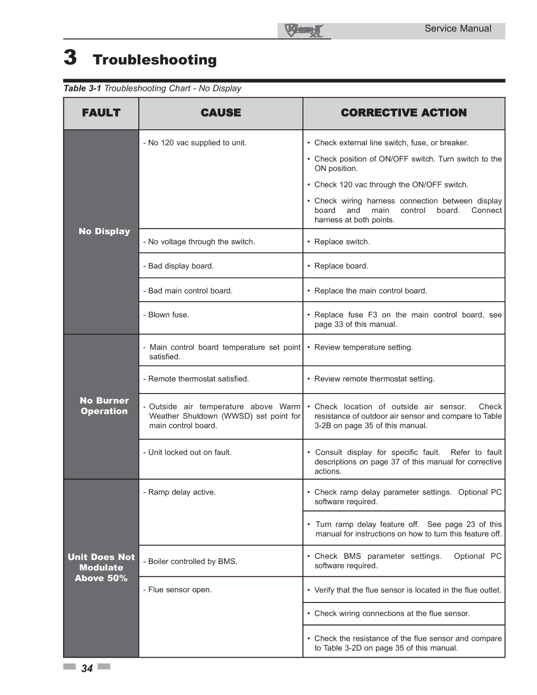
Table
FAULT | CAUSE |
|
| CORRECTIVE ACTION |
| |||||
|
|
|
|
| ||||||
| - No 120 vac supplied to unit. | • | Check external line switch, fuse, or breaker. |
| ||||||
|
| • | Check position of ON/OFF switch. Turn switch to the | |||||||
|
|
| ON position. |
|
|
|
|
| ||
|
| • Check 120 vac through the ON/OFF switch. |
| |||||||
|
| • Check | wiring | harness | connection | between display | ||||
|
|
| board | and | main | control | board. | Connect | ||
|
|
| harness at both points. |
|
|
|
| |||
No Display |
|
|
|
|
|
|
|
|
| |
- No voltage through the switch. | • | Replace switch. |
|
|
|
| ||||
|
|
|
|
| ||||||
|
|
|
|
|
|
|
| |||
| - Bad display board. | • | Replace board. |
|
|
|
| |||
|
|
|
|
|
|
| ||||
| - Bad main control board. | • | Replace the main control board. |
|
|
| ||||
|
|
|
| |||||||
| - Blown fuse. | • | Replace fuse F3 on the main control board, see | |||||||
|
|
| page 33 of this manual. |
|
|
|
| |||
|
|
|
|
|
|
| ||||
| - Main control board temperature set point | • | Review temperature setting. |
|
|
| ||||
| satisfied. |
|
|
|
|
|
|
|
| |
|
|
|
|
|
| |||||
| - Remote thermostat satisfied. | • | Review remote thermostat setting. |
|
| |||||
No Burner |
|
|
|
|
|
|
|
|
| |
- Outside air temperature above Warm | • Check location of outside air sensor. Check | |||||||||
Operation | ||||||||||
Weather Shutdown (WWSD) set point for |
| resistance of outdoor air sensor and compare to Table | ||||||||
|
| |||||||||
| main control board. |
|
|
| ||||||
|
|
|
|
|
| |||||
| - Unit locked out on fault. | • | Consult display for specific fault. | Refer | to fault | |||||
|
|
| descriptions on page 37 of this manual for corrective | |||||||
|
|
| actions. |
|
|
|
|
| ||
|
|
|
| |||||||
| - Ramp delay active. | • | Check ramp delay parameter settings. Optional PC | |||||||
|
|
| software required. |
|
|
|
| |||
|
|
|
|
| ||||||
|
| • | Turn ramp delay feature off. | See page 23 of this | ||||||
|
|
| manual for instructions on how to turn this feature off. | |||||||
Unit Does Not |
|
| ||||||||
- Boiler controlled by BMS. | • Check BMS parameter settings. Optional PC | |||||||||
|
|
|
|
|
|
|
| |||
Modulate |
|
| software required. |
|
|
|
| |||
Above 50% |
|
|
|
|
|
|
|
|
| |
- Flue sensor open. | • | Verify that the flue sensor is located in the flue outlet. | ||||||||
| ||||||||||
|
|
|
|
| ||||||
|
| • | Check wiring connections at the flue sensor. |
| ||||||
|
|
|
| |||||||
|
| • | Check the resistance of the flue sensor and compare | |||||||
|
|
| to Table |
| ||||||
|
|
|
|
|
|
|
|
|
| |
![]() 34
34 ![]()
