Service Manual
3Troubleshooting (continued)
Checking temperature sensors
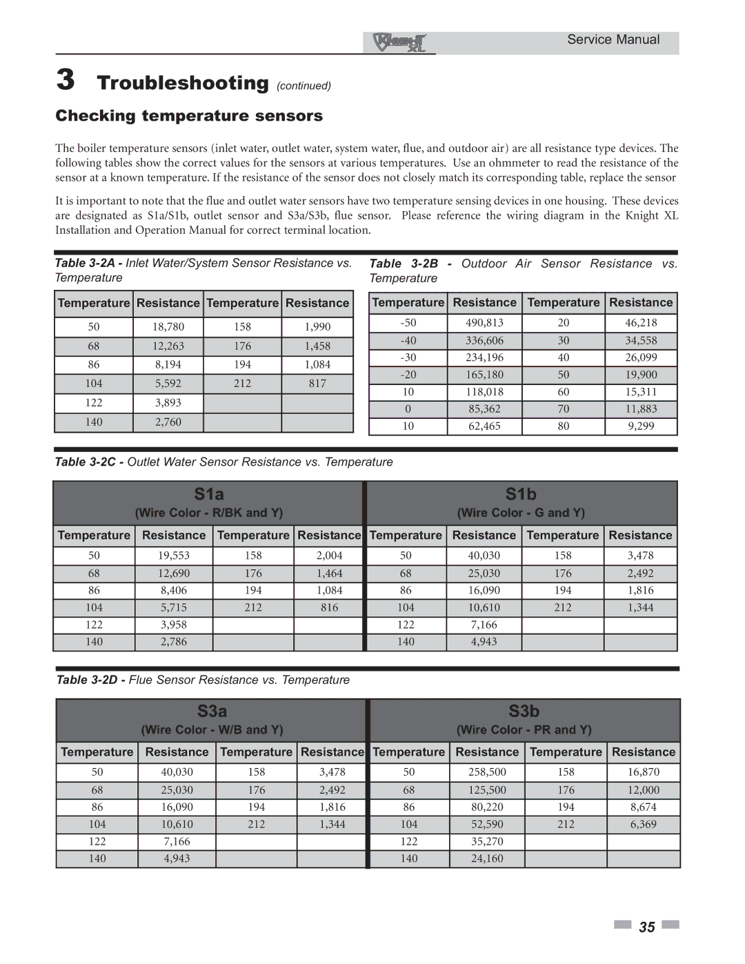
The boiler temperature sensors (inlet water, outlet water, system water, flue, and outdoor air) are all resistance type devices. The following tables show the correct values for the sensors at various temperatures. Use an ohmmeter to read the resistance of the sensor at a known temperature. If the resistance of the sensor does not closely match its corresponding table, replace the sensor
It is important to note that the flue and outlet water sensors have two temperature sensing devices in one housing. These devices are designated as S1a/S1b, outlet sensor and S3a/S3b, flue sensor. Please reference the wiring diagram in the Knight XL Installation and Operation Manual for correct terminal location.
Table
Temperature | Resistance | Temperature | Resistance |
|
|
|
|
50 | 18,780 | 158 | 1,990 |
|
|
|
|
68 | 12,263 | 176 | 1,458 |
86 | 8,194 | 194 | 1,084 |
|
|
|
|
104 | 5,592 | 212 | 817 |
122 | 3,893 |
|
|
140 | 2,760 |
|
|
|
|
|
|
Table
Temperature | Resistance | Temperature | Resistance |
|
|
|
|
490,813 | 20 | 46,218 | |
|
|
|
|
336,606 | 30 | 34,558 | |
234,196 | 40 | 26,099 | |
|
|
|
|
165,180 | 50 | 19,900 | |
10 | 118,018 | 60 | 15,311 |
|
|
|
|
0 | 85,362 | 70 | 11,883 |
10 | 62,465 | 80 | 9,299 |
|
|
|
|
Table
|
| S1a |
|
| S1b |
|
|
| ||
|
| (Wire Color - R/BK and Y) |
|
| (Wire Color - G and Y) |
|
|
| ||
|
|
|
|
|
|
|
|
|
|
|
| Temperature | Resistance | Temperature | Resistance | Temperature | Resistance | Temperature | Resistance |
|
|
|
|
|
|
|
|
|
|
|
|
|
| 50 | 19,553 | 158 | 2,004 | 50 | 40,030 | 158 | 3,478 |
|
|
|
|
|
|
|
|
|
|
|
|
|
| 68 | 12,690 | 176 | 1,464 | 68 | 25,030 | 176 | 2,492 |
|
|
| 86 | 8,406 | 194 | 1,084 | 86 | 16,090 | 194 | 1,816 |
|
|
|
|
|
|
|
|
|
|
|
|
|
| 104 | 5,715 | 212 | 816 | 104 | 10,610 | 212 | 1,344 |
|
|
| 122 | 3,958 |
|
| 122 | 7,166 |
|
|
|
|
|
|
|
|
|
|
|
|
|
|
|
| 140 | 2,786 |
|
| 140 | 4,943 |
|
|
|
|
|
|
|
|
|
|
|
|
|
|
|
|
|
|
|
|
|
|
|
|
|
|
| Table |
|
|
|
|
|
| |||
|
|
|
|
|
|
|
|
|
|
|
|
| S3a |
|
| S3b |
|
|
| ||
|
| (Wire Color - W/B and Y) |
|
| (Wire Color - PR and Y) |
|
|
| ||
|
|
|
|
|
|
|
|
|
| |
| Temperature | Resistance | Temperature | Resistance | Temperature | Resistance | Temperature | Resistance |
| |
|
|
|
|
|
|
|
|
|
|
|
| 50 | 40,030 | 158 | 3,478 | 50 | 258,500 | 158 | 16,870 |
|
|
|
|
|
|
|
|
|
|
|
|
|
| 68 | 25,030 | 176 | 2,492 | 68 | 125,500 | 176 | 12,000 |
|
|
| 86 | 16,090 | 194 | 1,816 | 86 | 80,220 | 194 | 8,674 |
|
|
|
|
|
|
|
|
|
|
|
|
|
| 104 | 10,610 | 212 | 1,344 | 104 | 52,590 | 212 | 6,369 |
|
|
| 122 | 7,166 |
|
| 122 | 35,270 |
|
|
|
|
|
|
|
|
|
|
|
|
|
|
|
| 140 | 4,943 |
|
| 140 | 24,160 |
|
|
|
|
|
|
|
|
|
|
|
|
|
|
|
![]() 35
35 ![]()
