Service Manual
3Troubleshooting
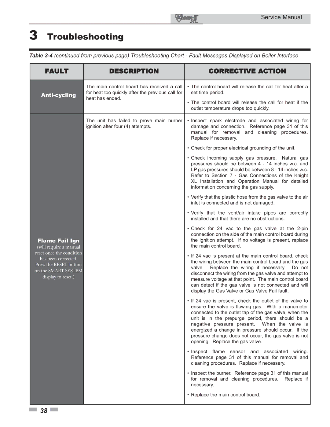
Table
FAULT | DESCRIPTION | CORRECTIVE ACTION |
|
|
|
| The main control board has received a call | • The control board will release the call for heat after a |
| for heat too quickly after the previous call for | set time period. |
heat has ended. |
| |
| • The control board will release the call for heat if the | |
|
| |
|
| outlet temperature drops too quickly. |
|
|
|
| The unit has failed to prove main burner | • Inspect spark electrode and associated wiring for |
| ignition after four (4) attempts. | damage and connection. Reference page 31 of this |
|
| manual for removal and cleaning procedures. |
|
| Replace if necessary. |
|
| • Check for proper electrical grounding of the unit. |
|
| • Check incoming supply gas pressure. Natural gas |
|
| pressures should be between 4 - 14 inches w.c. and |
|
| LP gas pressures should be between 8 - 14 inches w.c. |
|
| Refer to Section 7 - Gas Connections of the Knight |
|
| XL Installation and Operation Manual for detailed |
|
| information concerning the gas supply. |
|
| • Verify that the plastic hose from the gas valve to the air |
|
| inlet is connected and is not damaged. |
|
| • Verify that the vent/air intake pipes are correctly |
|
| installed and that there are no obstructions. |
|
| • Check for 24 vac to the gas valve at the |
Flame Fail Ign |
| connection on the side of the main control board during |
| the ignition attempt. If no voltage is present, replace | |
(will require a manual |
| the main control board. |
reset once the condition |
| • If 24 vac is present at the main control board, check |
has been corrected. |
| |
| the wiring between the main control board and the gas | |
Press the RESET button |
| |
| valve. Replace the wiring if necessary. Do not | |
on the SMART SYSTEM |
| |
| disconnect the wiring from the gas valve and attempt to | |
display to reset.) |
| |
| measure voltage at that point. The main control board | |
|
| |
|
| can detect if the gas valve is not connected and will |
|
| display the Gas Valve or Gas Valve Fail fault. |
|
| • If 24 vac is present, check the outlet of the valve to |
|
| ensure the valve is flowing gas. With a manometer |
|
| connected to the outlet tap of the gas valve, when the |
|
| unit is in the prepurge period, there should be a |
|
| negative pressure present. When the valve is |
|
| energized a change in pressure should occur. If the |
|
| pressure change does not occur, the gas valve is not |
|
| opening. Replace the gas valve. |
|
| • Inspect flame sensor and associated wiring. |
|
| Reference page 31 of this manual for removal and |
|
| cleaning procedures. Replace if necessary. |
|
| • Inspect the burner. Reference page 31 of this manual |
|
| for removal and cleaning procedures. Replace if |
|
| necessary. |
|
| • Replace the main control board. |
|
|
|
![]() 38
38 ![]()