402 - 2072 specifications
The Lochinvar 402 - 2072 is a versatile and highly efficient boiler designed to meet the heating demands of modern residential and commercial applications. This model stands out due to its innovative technologies, advanced features, and a high level of reliability, making it an ideal choice for consumers looking for an enduring and economical heating solution.One of the primary characteristics of the Lochinvar 402 - 2072 is its impressive energy efficiency. With an exceptional annual fuel utilization efficiency (AFUE) rating, this boiler ensures minimal energy waste, allowing homeowners and business operators to save significantly on their energy bills. The model incorporates advanced condensing technology that enables it to extract heat from the combustion gases, maximizing heat transfer and reducing emissions.
The Lochinvar 402 - 2072 is built with a robust stainless steel construction that enhances durability and resilience against corrosion and other environmental factors. This material not only prolongs the lifespan of the unit but also contributes to its outstanding thermal efficiency. Additionally, the boiler's compact design allows for flexible installation options, making it suitable for various spaces, including tight utility rooms and basements.
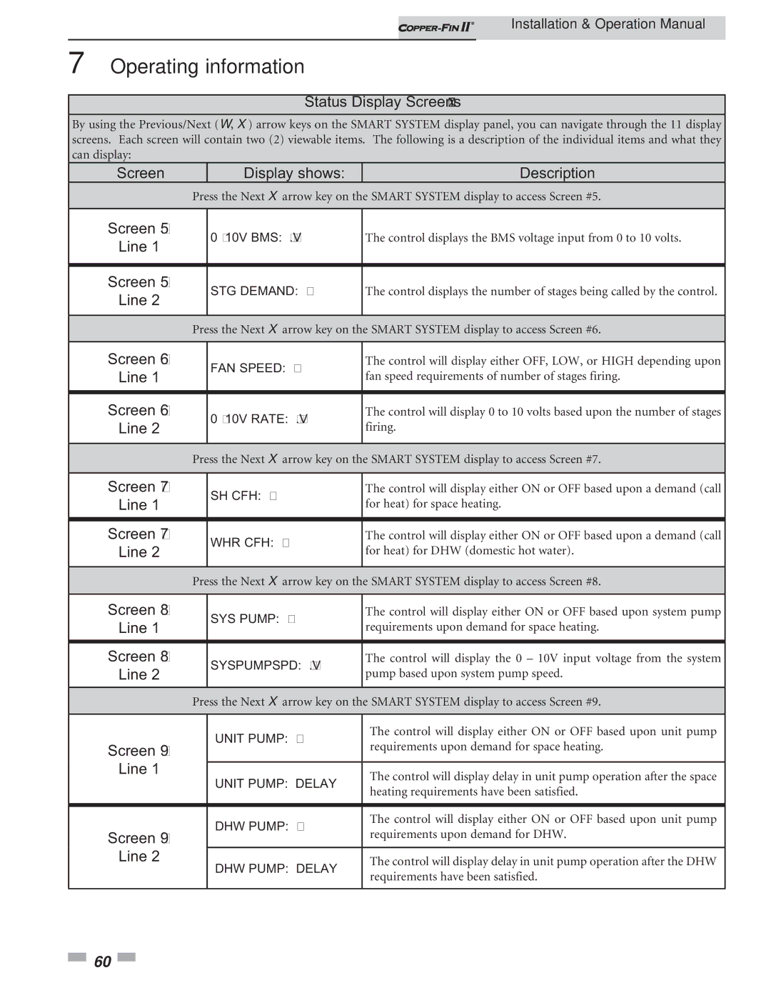
Equipped with a user-friendly control interface, the Lochinvar 402 - 2072 allows for easy monitoring and adjustment of settings. Its advanced digital display provides real-time data on system performance, ensuring the operator can maintain optimal performance and efficiency.
Another noteworthy feature is the unit's quiet operation. The design includes sound-dampening insulation and high-efficiency circulators, keeping noise to a minimum, which is an essential trait for both residential and commercial settings.
The Lochinvar 402 - 2072 is also designed with safety in mind. It incorporates multiple safety features including an automated vent damper, low water cutoff, and a comprehensive control system that monitors various operating conditions. This proactive approach to safety ensures that potential issues are identified and addressed before they become critical.
In conclusion, the Lochinvar 402 - 2072 boiler presents an exceptional combination of efficiency, durability, and user-friendly features. Its advanced condensing technology, stainless steel construction, and focus on safety make it a leading choice in the competitive boiler market, catering to the heating needs of a diverse range of applications while ensuring environmental responsibility. For those in search of a dependable and efficient heating solution, the Lochinvar 402 - 2072 is certainly worth considering.

