Installation & Operation Manual

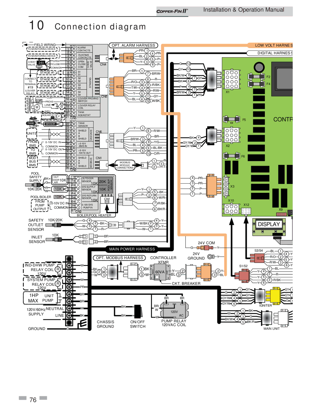
10 Connection diagram


FIELD WIRING


1

+

ALARM


OPT. ALARM HARNESS


LOW VOLT HARNES

TO MONITORING DEVICE


+

CONTACTS


PR

1


2

+


4

PR


DIGITAL HARNESS

TO MONITORING DEVICE


3

RUNTIME


BL

2


+

CONTACTS


5

P


OPEN

4

+

OPEN

WAY-3 VALVE


Y

3


3-WAY

24V


5


CN4


6

P


G

12


VALVE


COMMON

6

+

COM


CLOSE


+

CLOSE


STAGE #1


7

+

S1


BR

1


GY

10


8


7

BR/W


+

S1


BK/W

8


9


7 GY


F2


CONNECT

STAGE #3


12

+

S2


STAGING


9

R/BK


TERMINAL


+

S3


F4


TO

STAGE #2


10

+

S2


R/O

3

8

R


BK

6


11


#19


13

+

S3


T/W

4

10

R/W


P

4

3

W


(LOUVER

STAGE #4


+


BR/W

2

X1


RELAY)


14

S4


Y

5


1 PR


15

+

S4


CN5


11

GY


LOUVERS

M


COM


+

LOUVER PROVINGFIELD


BL

6


19

+

COIL


12

W/BK


PROVE


16

+

SWITCH


LINE


17

+

LOUVER RELAYWIRING


R

18


NEU


20

+

TANK


AQUASTAT


+

AQUASTAT


21


CONTR


CN3


F5


TANK


SENSOR


22

+

TANK


23

+

SENSOR


Y

1


+

SHIELD

CASCADE


6

R/W


BK


24

CN6


BR/W

3


+

SHIELD


UNITS


25

+

A


7

BR


4


26

+

B


FROM


0-10V DC IN

27

+


8

Y/G


GY/W

2


28

+0-10V


BL

4


1

X2


BMS


COMMON

29

+

-BMS IN


9

BL/BK


GY/W


TO


0-10V DC OUT

+

+0-10V


PR

5


30


10

O/R


BMS


COMMON

31

+

-RATE OUT


F6


MOD


+


CN1


32

SHIELD

MODBUS


MODULE


Y

3


BMS


34

+

SHIELD


1


BUS


33

A


MODBUS


R


+

B


2


T


35 CN2


CONNECTIONS


+


POOL


OUTDOOR


4


PR


SAFETY


OUT


SUPPLY BK

DOOR10K

1

+

SENSOR


20K

POOLSUP SENSOR


2


P


R

AIR


3

+

SENSOR


G


2

+


10K


3


PR

X3


10K/20K


10K


SYS SUPPLY


W


4

+


10K 10K


Y

1

5

BK


1


P


POOL/BOILER

10K


+

SYS RETURN


P

2


5


6

W/R


FROM

0-10V DC IN

6

+

SENSOR10K

CN1


X10


PUMP

7

+

0-10V SYS


7

R/BK


X12


OUTPUT

COMMON

+

- PUMP IN


8

BK/R


X9


8

CN2


BOILER/POOL HEATER


SAFETY

10K/20K


G

4

2

BK


4

Y


DISPLAY


OUTLET


W

3


W/BK 2


Y


1

R


W


3


SENSOR


1


INLET


10K


BR


SENSOR


BR


24V COM


MAIN POWER HARNESS


G


Y


S3/S4


BL

1


24V


Y


Y


R/O

4


OPT. MODBUS HARNESS


CONTROLLER

GROUND


2

Y


R/W

5

IND-DHW PUMP


W


XFMR


S1/S2

3

Y

R


BK

1


1 BK


1


6


RELAY COIL


120V 60VA 24V

Y

2


2 Y


BL


P


G 2


3 W


3


Y

4


R


120V


W

3


BL 3


BL


Y

2


SYSTEM PUMP


W


5

R/BK


3


RELAY COIL R


PR


CKT. BREAKER


Y

6


120V


G

1

GY


GY

1


1HP


UNIT


BR


2

GY


GY

3


BR


BR


GY/W

3


MAX

PUMP


BR


4

G


G

5


GY/W

5


BK


BR/


6

IGNITER


120V/60Hz NEUTRAL


W


W


120V


W

1

BK


SUPPLY


LINE


BK


BK


W


AC


2

G


BK/W

3


CHASSIS

ON/OFF


PUMP RELAY


4

BK/R


5


GROUND


G


GROUND

SWITCH


120VAC COIL


MAIN UNIT


76

Page 76
Image 76
Lochinvar 402 - 2072 operation manual Connection diagram, Digital Harness

402 - 2072 specifications

The Lochinvar 402 - 2072 is a versatile and highly efficient boiler designed to meet the heating demands of modern residential and commercial applications. This model stands out due to its innovative technologies, advanced features, and a high level of reliability, making it an ideal choice for consumers looking for an enduring and economical heating solution.

One of the primary characteristics of the Lochinvar 402 - 2072 is its impressive energy efficiency. With an exceptional annual fuel utilization efficiency (AFUE) rating, this boiler ensures minimal energy waste, allowing homeowners and business operators to save significantly on their energy bills. The model incorporates advanced condensing technology that enables it to extract heat from the combustion gases, maximizing heat transfer and reducing emissions.

The Lochinvar 402 - 2072 is built with a robust stainless steel construction that enhances durability and resilience against corrosion and other environmental factors. This material not only prolongs the lifespan of the unit but also contributes to its outstanding thermal efficiency. Additionally, the boiler's compact design allows for flexible installation options, making it suitable for various spaces, including tight utility rooms and basements.

Equipped with a user-friendly control interface, the Lochinvar 402 - 2072 allows for easy monitoring and adjustment of settings. Its advanced digital display provides real-time data on system performance, ensuring the operator can maintain optimal performance and efficiency.

Another noteworthy feature is the unit's quiet operation. The design includes sound-dampening insulation and high-efficiency circulators, keeping noise to a minimum, which is an essential trait for both residential and commercial settings.

The Lochinvar 402 - 2072 is also designed with safety in mind. It incorporates multiple safety features including an automated vent damper, low water cutoff, and a comprehensive control system that monitors various operating conditions. This proactive approach to safety ensures that potential issues are identified and addressed before they become critical.

In conclusion, the Lochinvar 402 - 2072 boiler presents an exceptional combination of efficiency, durability, and user-friendly features. Its advanced condensing technology, stainless steel construction, and focus on safety make it a leading choice in the competitive boiler market, catering to the heating needs of a diverse range of applications while ensuring environmental responsibility. For those in search of a dependable and efficient heating solution, the Lochinvar 402 - 2072 is certainly worth considering.