DECK MECHANISM ADJUSTMENT
1)After completing Step
(1)If folding or curling is observed at the bottom of the
(2)If folding or curling is observed at the top of it then slowly turn the Tilt Adjustment Screw(C) in the counterclockwise direction.
NOTE:
Check the RF envelope after adjusting the A/C Head, if the RF waveform differs from Fig.
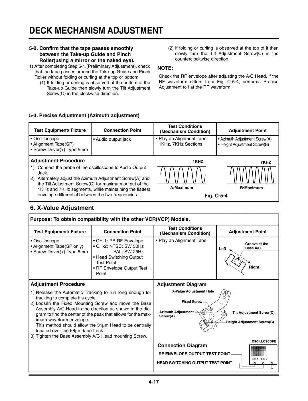
5-3. Precise Adjustment (Azimuth adjustment)
Test Equipment/ Fixture | Connection Point | Test Conditions | Adjustment Point |
(Mechanism Condition) | |||
|
|
|
|
• Oscilloscope | • Audio output jack | • Play an Alignment Tape | • Azimuth Adjustment Screw(A) |
• Alignment Tape(SP) |
| 1KHz, 7KHz Sections | • Height Adjustment Screw(B) |
•Screw Driver(+) Type 5mm
Adjustment Procedure
1)Connect the probe of the oscilloscope to Audio Output Jack.
2)Alternately adjust the Azimuth Adjustment Screw(A) and the Tilt Adjustment Screw(C) for maximum output of the 1KHz and 7KHz segments, while maintaining the flattest envelope differential between the two frequencies.
1KHZ |
| 7KHZ |
|
|
|
A:Maximum | B:Maximum |
Fig. C-5-4
6. X-Value Adjustment
Purpose: To obtain compatibility with the other VCR(VCP) Models.
Test Equipment/ Fixture | Connection Point | Test Conditions |
| Adjustment Point |
(Mechanism Condition) |
| |||
|
|
|
| |
|
|
|
|
|
• Oscilloscope | • | • Play an Alignment Tape |
| Groove at the |
• Alignment Tape(SP only) | • |
|
| |
| Left | Base A/C | ||
• Screw Driver(+) Type 5mm | PAL: SW 25Hz |
| ||
|
|
| ||
| • Head Switching Output |
|
|
|
| Test Point |
|
| Right |
| • RF Envelope Output Test |
|
| |
| Point |
|
|
|
|
|
|
|
|
Adjustment Procedure | Adjustment Diagram |
| |
1) Release the Automatic Tracking to run long enough for |
| ||
tracking to complete it’s cycle. | Fixed Screw |
| |
2) Loosen the Fixed Mounting Screw and move the Base |
| ||
|
| ||
Assembly A/C Head in the direction as shown in the dia- | Azimuth Adjustment | Tilt Adjustment Screw(C) | |
gram to find the center of the peak that allows for the max- | |||
Screw(A) |
| ||
imum waveform envelope. |
| ||
Height Adjustment Screw(B) | |||
This method should allow the 31µm Head to be centrally | |||
|
| ||
located over the 58µm tape track. |
|
| |
3) Tighten the Base Assembly A/C Head mounting Screw. |
|
| |
| Connection Diagram | OSCILLOSCOPE | |
|
| ||
| RF ENVELOPE OUTPUT TEST POINT |
| |
| HEAD SWITCHING OUTPUT TEST POINT | ||
|
| ||