DECK MECHANISM ADJUSTMENT
7. Adjustment after Replacing Drum Assembly (Video Heads)
Purpose: To correct for shift in the Roller Guide and X value after replacing the Drum.
Test Equipment/ Fixture | Connection Point | Test Conditions | Adjustment Points |
(Mechanism Condition) | |||
• Oscilloscope | • | • Play the Blank Tape | • Guide Roller Precise |
• Alignment Tapes | • | • Play an Alignment Tape | Adjustment |
• Blank Tape | PAL: SW 25Hz |
| • Switching Point |
• Post Height Adjusting Driver | • Head Switching Output |
| • Tracking Preset |
• Screw Driver(+) Type 5mm | Test Point |
| • |
•RF Envelope Output Test Point
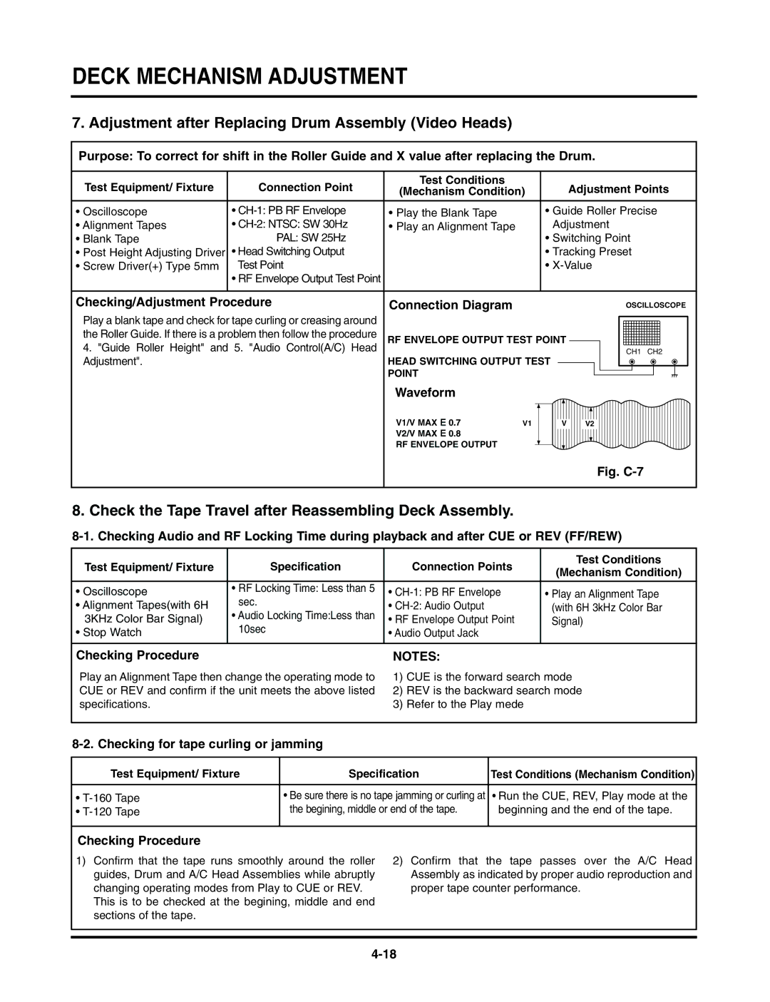
Checking/Adjustment Procedure |
|
|
|
|
|
|
|
|
|
|
|
|
|
|
|
|
|
|
|
|
|
|
|
|
|
|
|
|
|
|
|
|
|
|
|
|
|
|
|
|
|
|
|
|
|
|
|
|
|
|
|
|
|
|
|
|
|
| Connection Diagram |
|
|
|
|
|
|
|
|
|
|
|
|
|
|
|
|
|
|
|
|
|
|
|
|
|
|
|
|
|
| OSCILLOSCOPE | |||||||||||||||||||||||||
Play a blank tape and check for tape curling or creasing around |
|
|
|
|
|
|
|
|
|
|
|
|
|
|
|
|
|
|
|
|
|
|
|
|
|
|
|
|
|
|
|
|
|
|
|
|
|
|
|
|
|
|
|
|
|
|
|
|
|
|
|
|
|
|
|
|
|
|
|
|
|
|
|
|
|
|
|
|
|
|
|
|
|
|
|
|
|
|
|
|
|
|
|
|
|
|
|
|
|
|
|
|
|
|
|
|
|
|
|
|
|
|
|
|
|
|
|
|
|
|
|
|
|
| |
|
|
|
|
|
|
|
|
|
|
|
|
|
|
|
|
|
|
|
|
|
|
|
|
|
|
|
|
|
|
|
|
|
|
|
|
|
|
|
|
|
|
|
|
|
|
|
|
|
|
|
|
|
|
|
|
| |
the Roller Guide. If there is a problem then follow the procedure |
|
|
|
|
|
|
|
|
|
|
|
|
|
|
|
|
|
|
|
|
|
|
|
|
|
|
|
|
|
|
|
|
|
|
|
|
|
|
|
|
|
|
|
|
|
|
|
|
|
|
|
|
|
|
|
|
|
RF ENVELOPE OUTPUT TEST POINT |
|
|
|
|
|
|
|
|
|
|
|
|
|
|
|
|
|
|
|
|
|
|
|
|
|
|
|
|
|
|
|
|
|
|
|
|
|
|
|
|
|
| |||||||||||||||
4. "Guide Roller Height" and 5. "Audio Control(A/C) Head |
|
|
|
|
|
|
|
|
|
|
|
|
|
|
|
|
|
|
|
|
|
|
|
|
|
|
|
|
|
|
|
|
|
|
|
|
|
|
|
|
|
| |||||||||||||||
|
|
|
|
|
|
|
|
|
|
|
|
|
|
|
|
|
|
|
|
|
|
|
|
|
|
|
|
|
|
|
|
|
| CH1 CH2 | |||||||||||||||||||||||
|
|
|
|
|
|
|
|
|
|
|
|
|
|
|
|
|
|
|
|
|
|
|
|
|
|
|
|
|
|
|
|
| |||||||||||||||||||||||||
Adjustment". |
| HEAD SWITCHING OUTPUT TEST |
|
|
|
|
|
|
|
|
|
|
|
|
|
|
|
|
|
|
|
|
|
|
|
|
|
|
|
|
|
|
|
|
|
|
|
|
|
|
|
|
|
|
|
|
|
|
|
| |||||||
|
| POINT |
|
|
|
|
|
|
|
|
|
|
|
|
|
|
|
|
|
|
|
|
|
|
|
|
|
|
|
|
|
|
|
|
|
|
|
|
|
|
|
|
|
|
|
|
|
|
|
|
|
|
|
|
| ||
|
|
|
|
|
|
|
|
|
|
|
|
|
|
|
|
|
|
|
|
|
|
|
|
|
|
|
|
|
|
|
|
|
|
|
|
|
|
|
|
|
|
|
|
|
|
|
|
|
|
|
|
|
| ||||
|
|
|
|
|
|
|
|
|
|
|
|
|
|
|
|
|
|
|
|
|
|
|
|
|
|
|
|
|
|
|
|
|
|
|
|
|
|
|
|
|
|
|
|
|
|
|
|
|
|
|
|
|
|
|
|
|
|
|
|
| Waveform |
|
|
|
|
|
|
|
|
|
|
|
|
|
|
|
|
|
|
|
|
|
|
|
|
|
|
|
|
|
|
|
|
|
|
|
|
|
|
|
|
|
|
|
|
|
|
|
|
|
|
|
|
| |
|
|
|
|
|
|
|
|
|
|
|
|
|
|
|
|
|
|
|
|
|
|
|
|
|
|
|
|
|
|
|
|
|
|
|
|
|
|
|
|
|
|
|
|
|
|
|
|
|
|
|
|
|
|
| |||
|
|
| V1/V MAX E 0.7 |
|
|
|
|
|
|
|
|
|
|
|
|
|
|
|
|
|
|
|
|
|
|
|
|
|
|
|
|
|
|
|
|
|
|
|
|
|
|
|
|
|
|
|
|
|
|
|
|
|
|
|
| ||
|
|
|
| V1 |
|
|
|
| V |
|
|
|
|
|
| V2 |
|
|
|
|
|
|
|
|
|
|
|
|
|
|
|
|
|
|
|
|
|
|
|
|
|
|
|
|
|
|
|
| |||||||||
|
|
| V2/V MAX E 0.8 |
|
|
|
|
|
|
|
|
|
|
|
|
|
|
|
|
|
|
|
|
|
|
|
|
|
|
|
|
|
|
|
|
|
|
|
|
|
|
|
|
|
|
|
|
|
|
|
|
|
|
|
|
|
|
|
|
| RF ENVELOPE OUTPUT |
|
|
|
|
|
|
|
|
|
|
|
|
|
|
|
|
|
|
|
|
|
|
|
|
|
|
|
|
|
|
|
|
|
|
|
|
|
|
|
|
|
|
|
|
|
|
|
|
|
|
|
|
|
|
|
|
|
|
|
|
|
|
|
|
|
|
|
|
|
|
|
|
|
|
|
|
|
|
|
|
|
|
|
|
|
|
|
|
|
|
|
|
|
|
|
|
|
|
|
|
|
|
|
|
|
|
|
|
|
|
|
|
Fig. C-7
8. Check the Tape Travel after Reassembling Deck Assembly.
Test Equipment/ Fixture | Specification | Test Equipment | Test Conditions |
Connection Points | (Mechanism Condition) | ||
|
| Connection Points | |
• Oscilloscope | • RF Locking Time: Less than 5 | • | • Play an Alignment Tape |
• Alignment Tapes(with 6H | sec. | • | (with 6H 3kHz Color Bar |
3KHz Color Bar Signal) | • Audio Locking Time:Less than | • RF Envelope Output Point | Signal) |
• Stop Watch | 10sec | • Audio Output Jack |
|
|
|
|
|
Checking Procedure | NOTES: | |
Play an Alignment Tape then change the operating mode to | 1) | CUE is the forward search mode |
CUE or REV and confirm if the unit meets the above listed | 2) | REV is the backward search mode |
specifications. | 3) | Refer to the Play mede |
8-2. Checking for tape curling or jamming
Test Equipment/ Fixture | Specification | Test ConditionsVCR(VCP)(MechanismState Condition) |
|
|
|
• | • Be sure there is no tape jamming or curling at | • Run the CUE, REV, Play mode at the |
• | the begining, middle or end of the tape. | beginning and the end of the tape. |
|
|
|
Checking Procedure
1) Confirm that the tape runs smoothly around the roller | 2) Confirm that the tape passes over the A/C Head |
guides, Drum and A/C Head Assemblies while abruptly | Assembly as indicated by proper audio reproduction and |
changing operating modes from Play to CUE or REV. | proper tape counter performance. |
This is to be checked at the begining, middle and end |
|
sections of the tape. |
|