SECTION3 ELECTRICAL
ELECTRICAL ADJUSTMENT PROCEDURES
1. PG ADJUSTMENT
MODE | SPECIFICATION | OBJECT MEASURED | OBJECT ADJUSTED |
|
|
|
|
PLAYBACK IN SP | PG : 416 ± 20 sec | V.OUT JACK | VR501 |
|
|
|
|
1. Connect
and adjust it to
2.Connect
(In case of 10:1 Probe, adjust it 50
3.Adjust time of the oscilloscope to 0.1 msec.
4.Adjust the range between FLLING EDGE part of video vertical trigger signal and video vertical trigger signal to the specification(416±20 sec) with changing VR501.
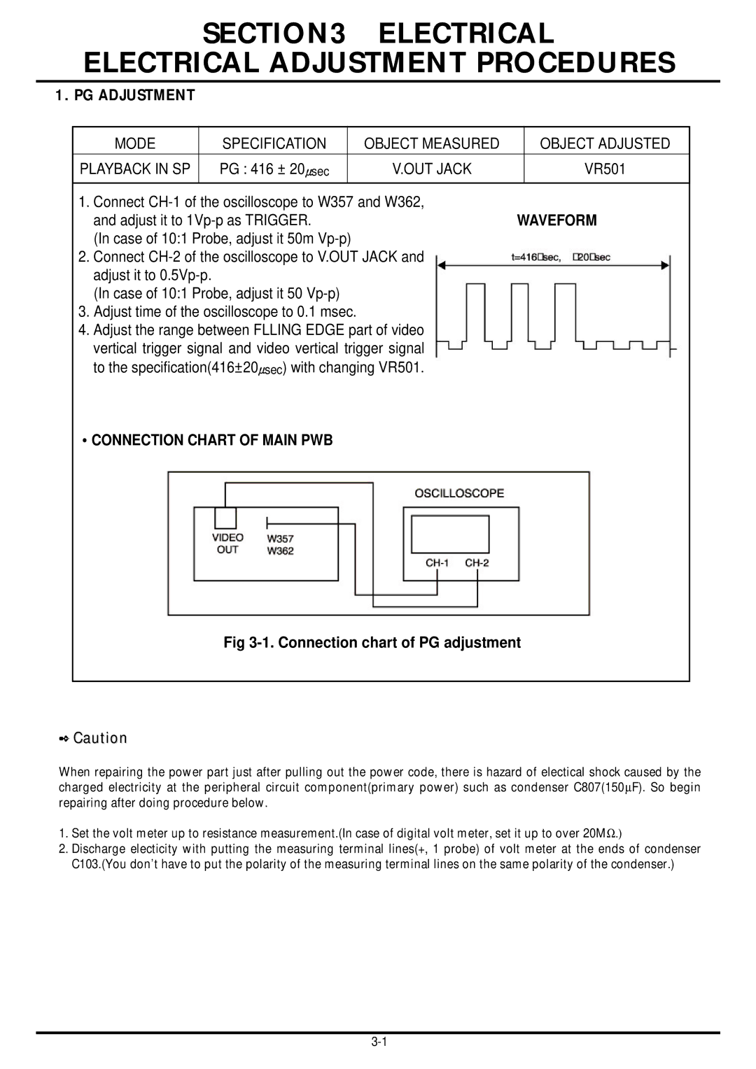
•CONNECTION CHART OF MAIN PWB
Fig 3-1. Connection chart of PG adjustment
✒Caution
When repairing the power part just after pulling out the power code, there is hazard of electical shock caused by the charged electricity at the peripheral circuit component(primary power) such as condenser C807(150∝F). So begin repairing after doing procedure below.
1.Set the volt meter up to resistance measurement.(In case of digital volt meter, set it up to over 20MΩ.)
2.Discharge electicity with putting the measuring terminal lines(+, 1 probe) of volt meter at the ends of condenser C103.(You don’t have to put the polarity of the measuring terminal lines on the same polarity of the condenser.)