KEY
Table of Contents
Summary
Front
Rear
Indicator Panel
VCR Function Indication
Terminal Signal Levels
IN/OUT Description
Summary Critical Parts Replacing Time Table
Cabinet & Main Frame Exploded Views
Cabinet & Main Frame Section Parts list
Cabinet and Main Frame Section
Packing Accessory Section Parts list
Packing & Accessory Section
PG Adjustment
Connection chart of PG adjustment
Power CircuitSMPS No 5.3 a
No 24
No 5.2 a to AVCP, Bias
When the drum moter stop
Video is unstable in PB mode
PB mode
Servo Circuit
When the capstan motor stops
Capstan motor stops
No Video in EE Mode
No Video in EE Mode
C Circuit
Clean the Drum Check the System Circuit IC501 Pin
Pin 16, 40, 55, 58, 87?
Is the EE signal normal?
Is 5V applied to the IC301 Pin 16, 40, 55, 58, 87?
No sound in PB Mode
No sound in EE Mode No sound in PB Mode
No sound in EE Mode
Audio Circuit
No sound in REC Mode
No sound in REC Mode
No cassette tape loading
SYSTEM/KEY Circuit Auto Stop
Auto Stop
No OSD display
No Key display
OSD Circuit
No F.OSD display
Electrical Block & Circuit Diagrams
Power Block Diagram
Power Clrcuit Diagram
Audio Block Diagram
C Block Diagram
V Circuit Diagram
Electrical Block & Circuit Diagrams
System Block Diagram
Electrical Block & Circuit Diagrams
System Clrcuit Diagram
Jack Clrcuit Diagram
KEY-BOARDCLRCUIT Diagram
Electrical Printed Circuit Diagrams
KEY 1 P.C.BOARD KEY 2 P.C.BOARD
Jack P.C.BOARD
Mechanism
Top View Bottom View
Part Fixing Type
Drum Assembly Fig. A-1-1
Drum Motor
Plate Top Fig. A-2-1
Fig. A-2-4
Bracket Assembly L/D Motor Fig. A-2-4
Gear Assembly Rack F/L Fig. A-2-5
Holder Assembly CST Fig.A-2-2
Arm Assembly F/L Fig. A-2-6
Base Assembly A/C Head
Arm Assembly
Cleaner
Head F/E Fig. A-3-2
Arm Assembly Tension Fig. A-4-3
Brake Assembly T Fig. A-4-1
Brake Assembly RS Fig. A-4-2
Reel S / Reel T Fig. A-4-4
Opener Lid Fig. A-5-2
Arm Assembly Pinch Fig. A-5-3
Lever T/up Fig. A-5-4 Arm T/up Fig. A-5-5
Brake Assembly Capstan
Lever F/R Fig. A-6-3
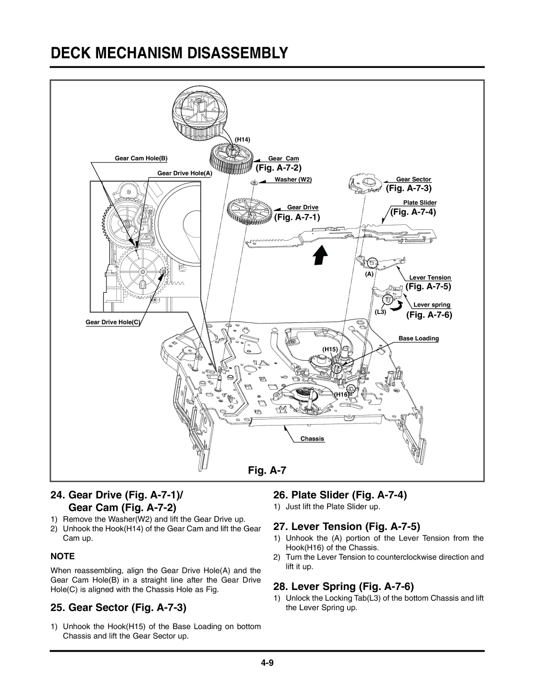
Lever Spring Fig. A-7-6
Gear Sector Fig. A-7-3
Lever Tension Fig. A-7-5
Just lift the Plate Slider up
Gear Assembly P2 Fig. A-8-1/ Gear Assembly P3 Fig. A-8-2
Base Assembly P2 Fig. A-8-3/ Base Assembly P3 Fig. A-8-4
Base Tension Fig. A-9-2
Base Loading Fig. A-9-1 Arm Assembly Idler Fig. A-9-3
Arm Assembly Idler
Base Tension Base Loading
Deck Mechanism Adjustment
Mechanism Alignment Position Check
Fig. C-1
Mechanism Condition
Checking Torque
Test Equipment/ Fixture Test Conditions
Torque Gauge 600g.cm ATG Cassette Torque Meter SRK-VHT-303
Guide Roller Height Adjustment
Head Assembly
Audio/Control A/C Head Adjustment
Adjustment Procedure/Diagrams
Head Base
Adjustment Procedure Adjustment Diagram
Value Adjustment
Precise Adjustment Azimuth adjustment
1KHZ 7KHZ
Adjustment after Replacing Drum Assembly Video Heads
Check the Tape Travel after Reassembling Deck Assembly
Check before starting repairs
Maintenance Procedure
Required Maintenance
Scheduled Maintenance
Cleaning
Chassis Bottom Chassis Top
Greasing
Gear Sector Gear Cam Base Loading Gear Drive
Gear AY, P2 & P3
Lever, F/R, Base, Tension
Base, Tension
Mechanism Troubleshooting Guide
Auto Stop PLAY/CUE/REV
Nono
Is the Belt ok?
Front Loading Mechanism
Cassette does not load
Exploded Views
Moving Mechanism
A11
RUN Date
NSP Not Service Part
Parts Section
LOCA.NO Description Specification Remarks
Description Specification
Assembly Section Remarks
Screw
Buzzer
LOCA.NO Description Specification Remark BATTERY,LITHIUM
Electrecal section
Capacitor
LOCA.NO Description Specification Remark
NP0 TS
Coil
Diode
Fuse
Digitron
Filter
Holder
R121 0RD1800F608
R3G6 0RD1800F608
R553 0RD2200F608
R610 0RD2701F608
Switch
LOCA.NO Description Specification
Remote Controller Receiver Remark
RESISTOR,DRAWING
TAL
Transformer
Varistor
Zener Diode