DECK MECHANISM ADJUSTMENT
4.Guide Roller Height Adjustment
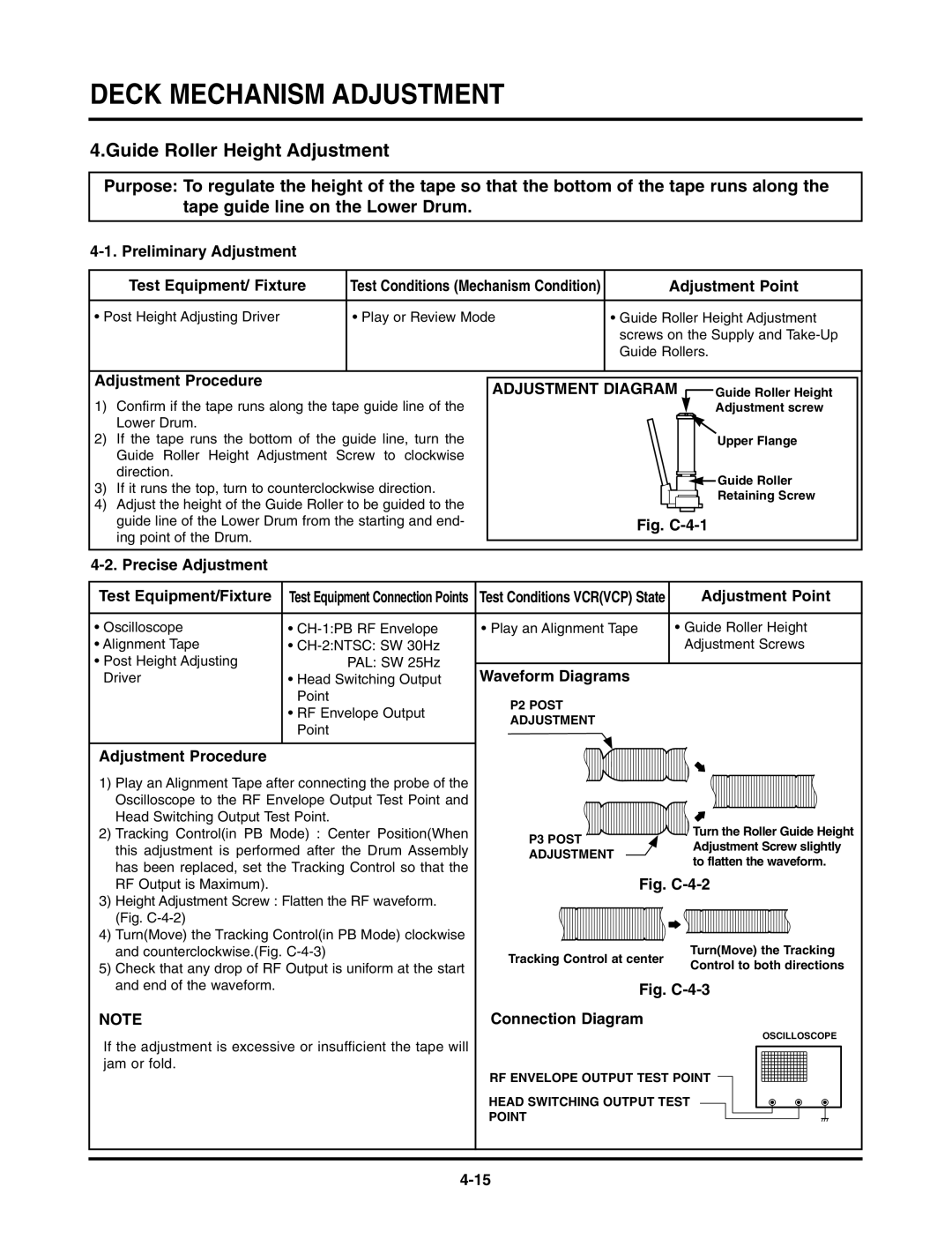
Purpose: To regulate the height of the tape so that the bottom of the tape runs along the tape guide line on the Lower Drum.
Test Equipment/ Fixture | Test Conditions (Mechanism Condition) | Adjustment Point |
|
|
|
• Post Height Adjusting Driver | • Play or Review Mode | • Guide Roller Height Adjustment |
|
| screws on the Supply and |
|
| Guide Rollers. |
|
|
|
Adjustment Procedure
1)Confirm if the tape runs along the tape guide line of the Lower Drum.
2)If the tape runs the bottom of the guide line, turn the Guide Roller Height Adjustment Screw to clockwise direction.
3)If it runs the top, turn to counterclockwise direction.
4)Adjust the height of the Guide Roller to be guided to the guide line of the Lower Drum from the starting and end- ing point of the Drum.
ADJUSTMENT DIAGRAM ![]() Guide Roller Height
Guide Roller Height
Adjustment screw
Upper Flange
![]()
![]() Guide Roller
Guide Roller
Retaining Screw
Fig. C-4-1
|
|
|
|
Test Equipment/Fixture | Test Equipment Connection Points | Test Conditions VCR(VCP) State | Adjustment Point |
• Oscilloscope | • | • Play an Alignment Tape | • Guide Roller Height |
• Alignment Tape | • |
| Adjustment Screws |
• Post Height Adjusting | PAL: SW 25Hz | Waveform Diagrams |
|
Driver | • Head Switching Output |
| |
| Point | P2 POST |
|
| • RF Envelope Output |
| |
| ADJUSTMENT |
| |
| Point |
| |
|
|
|
Adjustment Procedure
1)Play an Alignment Tape after connecting the probe of the Oscilloscope to the RF Envelope Output Test Point and
Head Switching Output Test Point. |
| Turn the Roller Guide Height | |
2) Tracking Control(in PB Mode) : Center Position(When | P3 POST | ||
this adjustment is performed after the Drum Assembly | Adjustment Screw slightly | ||
ADJUSTMENT | |||
to flatten the waveform. | |||
has been replaced, set the Tracking Control so that the |
| ||
| Fig. | ||
RF Output is Maximum). |
|
3)Height Adjustment Screw : Flatten the RF waveform. (Fig.
4)Turn(Move) the Tracking Control(in PB Mode) clockwise
and counterclockwise.(Fig. |
| Tracking Control at center | Turn(Move) the Tracking | |||||||
5) Check that any drop of RF Output is uniform at the start |
| Control to both directions | ||||||||
|
|
| ||||||||
and end of the waveform. |
| Fig. | ||||||||
NOTE |
|
|
|
|
|
|
|
|
|
|
| Connection Diagram |
|
|
|
|
|
|
| ||
If the adjustment is excessive or insufficient the tape will |
|
|
|
|
|
| OSCILLOSCOPE | |||
|
|
|
|
|
|
|
|
|
| |
|
|
|
|
|
|
|
|
|
| |
jam or fold. |
|
|
|
|
|
|
|
|
|
|
|
| RF ENVELOPE OUTPUT TEST POINT |
|
|
|
|
| |||
|
|
|
|
|
|
|
|
|
|
|
|
|
|
|
|
|
|
|
|
|
|
| HEAD SWITCHING OUTPUT TEST |
|
|
|
|
|
|
| ||
| POINT |
|
|
|
|
|
|
| ||
|
|
|
|
|
|
|
| |||
|
|
|
|
|
|
|
|
|
|
|