P 13/ 25
 Repair
[3]DISASSEMBLY/ASSEMBLY
[3]-6. Torque limiter section
DISASSEMBLING
(1)Disassemble Tool holder section. (Figs. 4 to 6 for BHR242/ Figs. 8 to 13 for BHR243.)
(2)Disassemble Change lever. (Figs. 27 to 29)
(3)Remove Gear housing section from Motor housing, and then remove Rotor section from Gear housing section.
(Figs. 31 to 33)
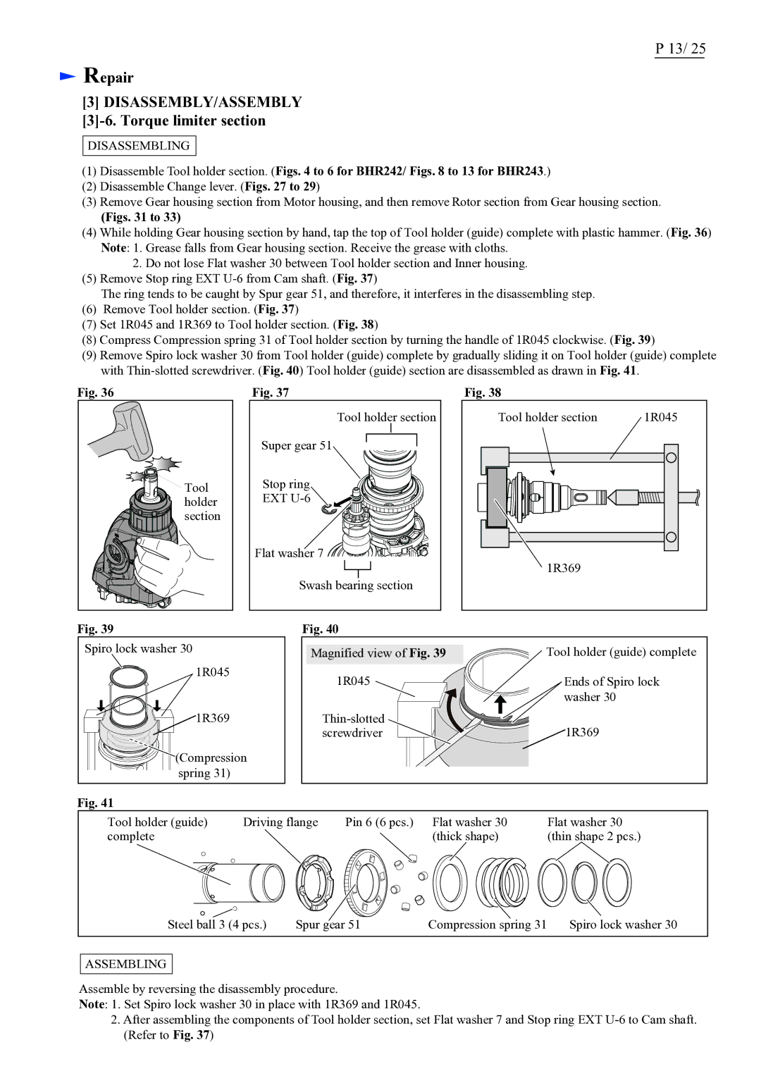
(4)While holding Gear housing section by hand, tap the top of Tool holder (guide) complete with plastic hammer. (Fig. 36) Note: 1. Grease falls from Gear housing section. Receive the grease with cloths.
2.Do not lose Flat washer 30 between Tool holder section and Inner housing.
(5)Remove Stop ring EXT
The ring tends to be caught by Spur gear 51, and therefore, it interferes in the disassembling step.
(6)Remove Tool holder section. (Fig. 37)
(7)Set 1R045 and 1R369 to Tool holder section. (Fig. 38)
(8)Compress Compression spring 31 of Tool holder section by turning the handle of 1R045 clockwise. (Fig. 39)
(9)Remove Spiro lock washer 30 from Tool holder (guide) complete by gradually sliding it on Tool holder (guide) complete with
Fig. 36
Tool |
holder |
section |
Fig. 37
Tool holder section |
Super gear 51 |
Stop ring |
EXT |
Flat washer 7 |
Swash bearing section |
Fig. 38
Tool holder section | 1R045 |
1R369 |
|
Fig. 39
Spiro lock washer 30
1R045
![]()
![]()
![]() 1R369
1R369
![]()
![]() (Compression
(Compression ![]()
![]()
![]() spring 31)
spring 31)
Fig. 40
Magnified view of Fig. 39 | Tool holder (guide) complete |
1R045 | Ends of Spiro lock |
| washer 30 |
1R369 | |
screwdriver |
Fig. 41
Tool holder (guide) | Driving flange | Pin 6 (6 pcs.) | Flat washer 30 | Flat washer 30 |
complete |
|
| (thick shape) | (thin shape 2 pcs.) |
Steel ball 3 (4 pcs.) | Spur gear 51 | Compression spring 31 | Spiro lock washer 30 |
ASSEMBLING
Assemble by reversing the disassembly procedure.
Note: 1. Set Spiro lock washer 30 in place with 1R369 and 1R045.
2.After assembling the components of Tool holder section, set Flat washer 7 and Stop ring EXT
