P 14/ 25
 Repair
[3] DISASSEMBLY/ASSEMBLY
[3]-6. Impact bolt in Torque limiter section
DISASSEMBLING
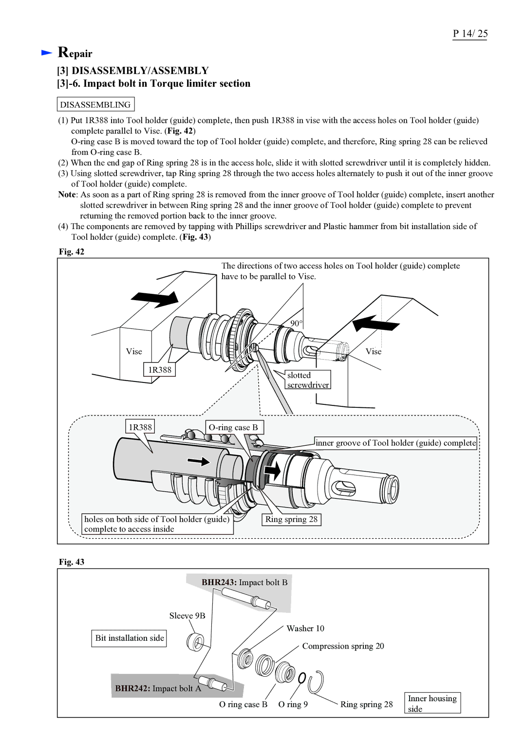
(1)Put 1R388 into Tool holder (guide) complete, then push 1R388 in vise with the access holes on Tool holder (guide) complete parallel to Vise. (Fig. 42)
(2)When the end gap of Ring spring 28 is in the access hole, slide it with slotted screwdriver until it is completely hidden.
(3)Using slotted screwdriver, tap Ring spring 28 through the two access holes alternately to push it out of the inner groove of Tool holder (guide) complete.
Note: As soon as a part of Ring spring 28 is removed from the inner groove of Tool holder (guide) complete, insert another
slotted screwdriver in between Ring spring 28 and the inner groove of Tool holder (guide) complete to prevent returning the removed portion back to the inner groove.
(4)The components are removed by tapping with Phillips screwdriver and Plastic hammer from bit installation side of Tool holder (guide) complete. (Fig. 43)
Fig. 42
The directions of two access holes on Tool holder (guide) complete have to be parallel to Vise.
| 90° |
Vise | Vise |
1R388 | slotted |
| |
| screwdriver |
1R388 |
inner groove of Tool holder (guide) complete
holes on both side of Tool holder (guide) | Ring spring 28 |
complete to access inside |
|
Fig. 43
BHR243: Impact bolt B
Sleeve 9B
Washer 10
Bit installation side
Compression spring 20
BHR242: Impact bolt A
O ring case B O ring 9 ![]() Ring spring 28
Ring spring 28
Inner housing side