P 11/ 25
 Repair
[3]DISASSEMBLY/ASSEMBLY
[3]-4. Rotor
DISASSEMBLING
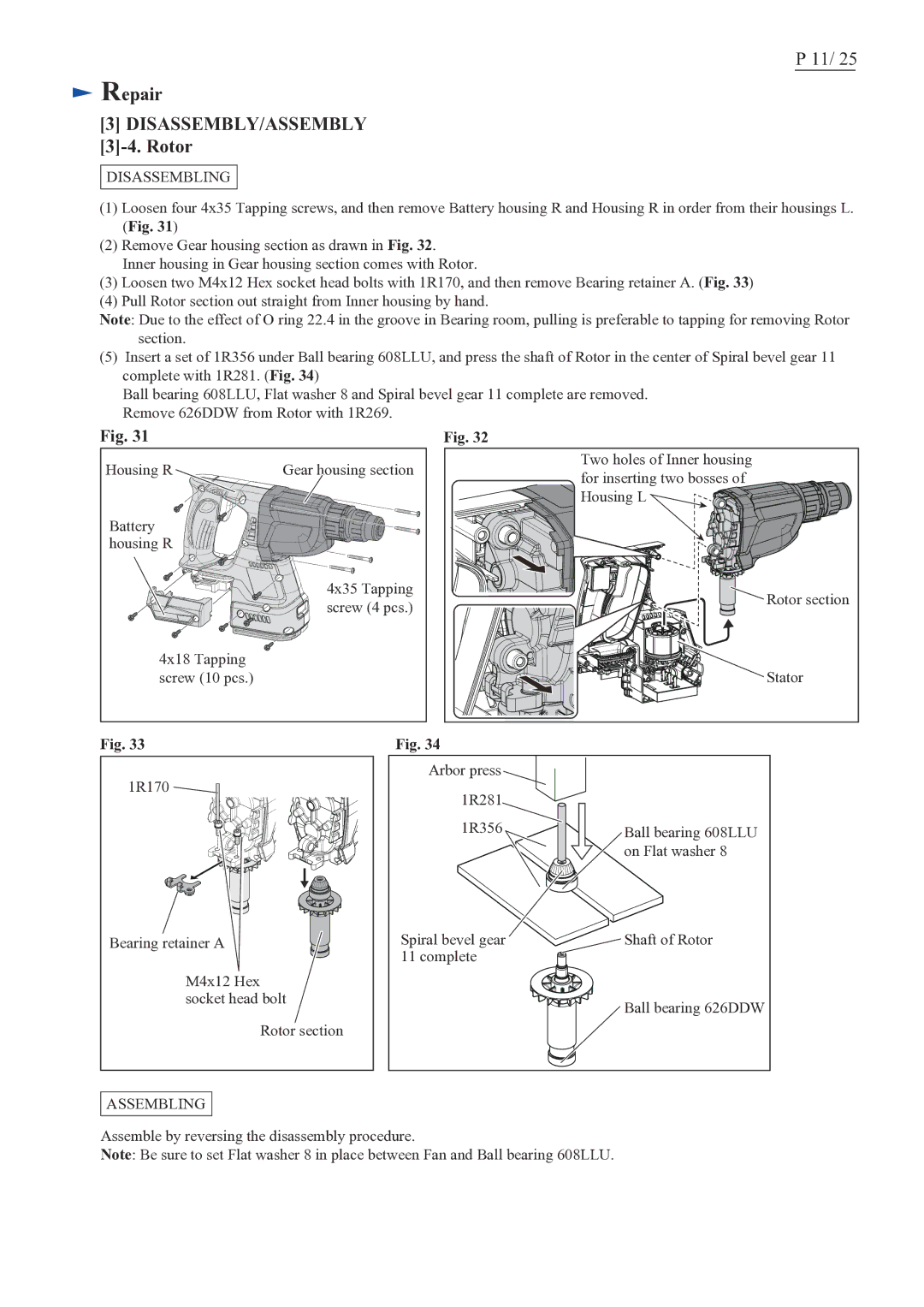
(1)Loosen four 4x35 Tapping screws, and then remove Battery housing R and Housing R in order from their housings L. (Fig. 31)
(2)Remove Gear housing section as drawn in Fig. 32.
Inner housing in Gear housing section comes with Rotor.
(3)Loosen two M4x12 Hex socket head bolts with 1R170, and then remove Bearing retainer A. (Fig. 33)
(4)Pull Rotor section out straight from Inner housing by hand.
Note: Due to the effect of O ring 22.4 in the groove in Bearing room, pulling is preferable to tapping for removing Rotor section.
(5)Insert a set of 1R356 under Ball bearing 608LLU, and press the shaft of Rotor in the center of Spiral bevel gear 11 complete with 1R281. (Fig. 34)
Ball bearing 608LLU, Flat washer 8 and Spiral bevel gear 11 complete are removed. Remove 626DDW from Rotor with 1R269.
Fig. 31 | Fig. 32 |
Housing R | Gear housing section |
Battery |
|
housing R |
|
| 4x35 Tapping |
| screw (4 pcs.) |
4x18 Tapping |
|
screw (10 pcs.) |
|
Fig. 33 | Fig. 34 |
Two holes of Inner housing for inserting two bosses of ![]() Housing L
Housing L ![]()
![]()
![]()
![]()
![]()
![]() Rotor section
Rotor section
![]()
![]()
![]()
![]()
![]()
![]()
![]()
![]()
![]()
![]()
![]()
![]()
![]()
![]()
![]()
![]() Stator
Stator
1R170 |
Bearing retainer A |
M4x12 Hex |
socket head bolt |
Rotor section |
ASSEMBLING |
Arbor press |
|
1R281 |
|
1R356 | Ball bearing 608LLU |
| on Flat washer 8 |
Spiral bevel gear | Shaft of Rotor |
11 complete |
|
| Ball bearing 626DDW |
Assemble by reversing the disassembly procedure.
Note: Be sure to set Flat washer 8 in place between Fan and Ball bearing 608LLU.
