P 23/ 25
 Circuit diagram
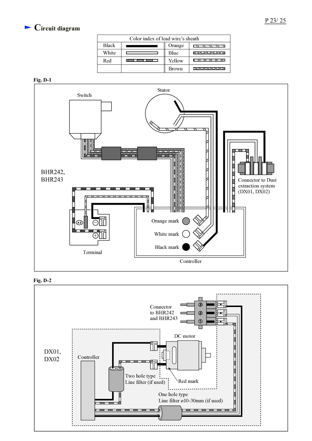
Color index of lead wire’s sheath
Black | Orange |
White | Blue |
Red | Yellow |
| Brown |
Fig. |
|
Switch | Stator |
| |
BHR242, |
|
BHR243 | Connector to Dust |
| extraction system |
| (DX01, DX02) |
| Orange mark |
| White mark |
Terminal | Black mark |
| |
| Controller |
Fig. |
|
DX01,
DX02
Connector to BHR242 and BHR243
DC motor
Controller
Two hole type | Red mark |
Line filter (if used) |
One hole type
Line filter